This Blog has Moved

This blog has moved to www.allyplm.com/blog

To stay up-to-date with the latest news, tips and tricks, product enhancements and maintenance packs for Siemens PLM Software solutions, visit our new site!

For resources for specific products, you can navigate directly to the product resource page:
... and more!
Showing posts with label NX CAD. Show all posts

Friday, July 24, 2015

Tip of the Week July 24

NX Tip of the Week
July 24, 2015

NX - Keyboard Shortcuts in NX
There are many keyboard shortcuts in NX that can help speed up your design and manufacturing processes.  Keyboard shortcuts save mouse travel and reduce the number of mouse clicks needed for a variety of functions in NX.  There are many predefined keyboard shortcuts within the system.  You can also customize the system to create your own keyboard shortcuts.  The steps below will show you where to locate the keyboard shortcuts that are already defined in the system and how to create your own keyboard shortcuts:

1)  Many common NX functions have keyboard shortcuts already assigned.  The keyboard shortcut can be seen in the "Tool Tip".  This example shows that "Ctrl+Alt+T" is the shortcut to orient to the Top view:


2)  To display a complete list of existing keyboard shortcuts go to Menu > Information > Custom Menu Bar > Shortcut Keys:


3)  You can also create your own shortcut keys by going to File > Customize:


4)  In the Customize dialog, select "Keyboard...":


5)  In the Customize Keyboard dialog, locate the Command you would like to assign a shortcut key.  Specify the shortcut key and then click "Assign".  In the example shown below the letter "G" is being assigned to the Generate command in the Manufacturing Environment:


Chad Varney
Application Engineer
Ally PLM Solutions, Inc.
Want more tips? Sign up HERE to receive our Tip of the Week.


Register for upcoming free NX webinars or learn more about Ally PLM Solutions.


Friday, July 10, 2015

Tip of the Week July 10

 NX Tip of the Week
July 10, 2015

NX - Fixing issues with opening NX files from Windows Explorer

If you have had multiple versions of NX on your PC in Windows Explorer, there are times you can't double click on the file and have it open. At times, NX may open but the file does not open or it errors out. You may have multiple versions of NX loaded and you need to have Windows Explorer open the file in a specific version of NX when you double click.  Here is how to change/fix this:
1)  Open a command prompt (Windows Start Menu then type cmd in the search window - a black window should appear).

2)  Type in the following:  assoc .prt

3)  You should see .prt=UGpartfile

4)  Next, type in the following:  ftype UGpartfile

5)  If all is correct, the NX 10.0 is the version which you want to open when you double click from Windows Explorer, then you will see:  
UGpartfile="C:\Program Files\Siemens\NX 10.0\UGII\ugs_router.exe"  -ug -use_file_dir  "%1"

6)  Or, if you had NX 7.5 previously installed and you uninstalled it, you may see:  UGpartfile="C:\Program Files\UGS\NX 7.5\UGII\ugs_router.exe"  -ug -use_file_dir  "%1". Then again, you may see something different or nothing at all.

7)  This would mean the ugs_router.exe from NX 7.5 is being used and not the proper NX version you would prefer. In your case, you want it to use NX 10 so you would do the following: 
In the command prompt for NX 10, type:  
ftype UGpartfile="C:\Program Files\Siemens\NX 10.0\UGII\ugs_router.exe"  -ug -use_file_dir "%1"
Note, NX 8 is the first version to use the Siemens directory and not UGS for the installation. If you have a 32 bit version of the product installed on a 64 bit machine, you will need to use C:\Program Files (x86)\Siemens\NX 8.0\UGII\ugs_router.exe. 

In addition, when starting NX by double-clicking on an NX part file in Windows Explorer and you want to stop the 'Routing to Application' dialog from appearing, try adding "-disable-cancel" to the ugs_router.exe: 
"C:\Program Files\Siemens\NX 10.0\UGII\ugs_router.exe"  -ug -use_file_dir -disable_cancel "%1"

As always, contact support@allyplm.com for more information or help.
Madison Rye
Application Engineering Manager
Ally PLM Solutions, Inc.

Want more tips? Sign up HERE to receive our Tip of the Week.

Register for upcoming free NX webinars or learn more about Ally PLM Solutions.

Thursday, June 25, 2015

Tip of the Week June 26


NX Tip of the Week
June 26, 2015

NX - Making Changes to Linear Dimensions on a Drawing Sheet
For this week's Tip of the Week, I will show you several options to tweak your existing linear dimension style. If you want global options, you need to change the parameters in drafting preferences on the template. I will show you this process in subsequent tips. In this example, I will focus on making changes to an existing linear dimension on a drawing sheet including inside orientation, outside orientation, text aligned to dimension line and dual dimension. 


The next step is common to all 4 dimension modes demonstrated within this tip - right click on the Dimension > Settings:

1) Inside dimension arrow orientation
    Choose Line/Arrow > Arrowhead.  Under Dimension Side 1, choose the In option.   

2)  Outside dimension arrow orientation
     Choose Line/Arrow > Arrowhead.  Under Dimension Side 1, choose the Out option:

3)  Text aligned to dimension option
     Expand Text within the Settings box then select Orientation and Location. From the dropdown, choose Text Aligned to Dimension Line:

4)  Dual dimension option
     Choose Dual then select the preferred unit:

Thank you!

Navjot Gill
Application Engineer
Ally PLM Solutions, Inc.

Want more tips? Sign up HERE to receive our Tip of the Week.


Register for upcoming free NX webinars or learn more about Ally PLM Solutions.


Friday, June 19, 2015

Tip of the Week June 19

 NX Tip of the Week
June 19, 2015

NX - Customize Columns and Export Information from NX
to an Excel Spreadsheet
There is a very useful option in NX that allows the user to export information from NX into an Excel spreadsheet. This can be used in NX CAM to export a list of tools, operations, and other information. This could be used in NX CAD to export a list of components in an assembly, model history, etc. The steps below will illustrate how to export machining information and also how to modify columns in the Operation Navigator in NX CAM. Customizing columns will allow you to export only the information needed for the spreadsheet.

1)  In the Manufacturing Environment, I am in the Program Order View. Notice the list of operations and the information listed in each column: 

2)  Right click below the operations in the Operation Navigator and then select "Export to Spreadsheet":

3)  Notice all of the information from the Operation Navigator is now listed in an Excel spreadsheet:

4)  Customize the columns by right clicking below the operations in the Operation Navigator and select "Columns" and check and uncheck the columns you want to display:

5)  Notice I have turned on the "Time" column and now the time of each operation is shown in the spreadsheet:

Chad Varney
Application Engineer
Ally PLM Solutions, Inc.

Want more tips? Sign up HERE to receive our Tip of the Week.
Register for upcoming free NX webinars or learn more about Ally PLM Solutions.

Friday, May 29, 2015

Tip of the Week May 29


NX Tip of the Week
May 29, 2015
NX - Getting the Area of a Closed Curve

In this week's Tip, we will look at how to get the area of closed curve on a drafting drawing.
1)  In the Drafting application, select Analysis > Advanced Mass Properties > Area using Curves:

2)  Select Boundary (Temporary):

3) Select the curves.

4) Click OK on the 2D Analysis dialog.

5) Set the desired tolerance. Click OK.

6) Select the 'Perimeter/Area' button to display the information.


Note: If the curves are not selectable in Step 3, expand the view first before beginning the Area using Curves command.
          a) Hover the cursor over the view boundary, select MouseButton3 > Expand

b)  To turn the Expanded View off, hover the cursor over the view boundary, select MouseButton3 > Expand.

I hope you find this tip useful, thank you.
Navjot Gill
Application Engineer
Ally PLM Solutions, Inc.

Want more tips? Sign up HERE to receive our Tip of the Week.

Register for upcoming free NX webinars or learn more about Ally PLM Solutions.

Friday, March 20, 2015

Tip of the Week March 20


NX Tip of the Week
March 20, 2015


NX - Ordinate Dimensioning in NX Modeling and Reusing it in Drafting

Today I will explain how to create ordinate dimensions within NX Modeling. I will also show how to reuse the dimensions in Drafting.
     
Ordinate Dimensioning in Modeling Application -


Result in Drafting Environment -

  • To get started, make sure the PMI option is turned ON. By default, it is turned OFF


  • Set the Model View to Work:    


  • Under the PMI Ordinate Dimension command, pick Single or Multiple Dimension.

  • With Single Dimension, use Select Origin where you pick any point. This is going to be the origin of the ordinate dimension.

  • I have selected the single dimension option to help pick one hole at a time:


  •  Start by picking the center of the holes and place them one at a time:


  • Now let's look at the Multiple Selection option. With Multiple Dimension, I can pick all the holes at once.

  • Change the option to Multiple Dimension and pick the origin:


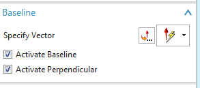
  •  Set the Baseline option:


  •  Before I start selecting the holes, the margins need to be defined. Click on the Define Margins command:


  •   


  •  Here are the options I selected for this example:


  •    


  •  Select the bottom left corner point as the origin:


  •    


  •  Follow the same procedure to get a horizontal margin:


  •  Baseline option step:


  •  Select all the holes by clicking on the center point of the circular edge.

  • Result:


  • Save the Model file.


  • Switch to the Drafting application and place the top model view on the sheet:


  • After placing the view, go to View Settings:


  • Make sure to change the settings to From Model View, click Apply:


  • Final Result:


    Navjot Gill 
    Application Engineer
    Ally PLM Solutions, Inc.

    Want more tips? Sign up HERE to receive our Tip of the Week.


    Thursday, August 8, 2013

    A Sneak Peak at NX 9


    At the recent Siemens PLM Connection Americas User Conference in Dallas, we began to describe our plans for the next release of NX™. We will deliver the next major release–NX 9–later in 2013.


    NX 9 will contain significant enhancements in CAD, CAE and CAM, and will offer notable productivity improvements in multiple areas. NX 9 will deliver new solutions that help you meet your product development challenges and deliver better products. Without going into specific command details, here are a few things you can expect from NX 9 for design.


    NX 9 will change how you work with 2D data. The introduction of synchronous technology 2D applies concepts of synchronous technology to 2D geometry to reduce the time it takes to make edits to 2D profiles. Imagine relational editing of both constrained and unconstrained geometry. It offers a productive way to work with large sketches that contain many curves and offers the ability to update dimensional constraints, preserving sketch integrity.


    NX 9 will help you achieve new levels of productivity in concept design because creation of freeform shapes will be faster and more flexible. Subdivision surfacing enables new levels of advanced surface creation, integration and speed. You’ll be able to quickly try alternative shapes and styles in order to be more innovative. It is intuitive and easy to use. It allows you to start off with a primitive shape. You then manipulate a surrounding “cage” to morph the shape as needed. The end product is high-quality B-surfaces in an editable NX feature.


    Synchronous technology in 3D also continues to be enhanced. With NX 9 you will be able to edit a shape by directly manipulating its edges instead of the usual method of editing its faces. Faces adjacent to the edges that you edit will adapt to follow their motion. NX 9 will also offer significant advancements in visualization with real-time race-traced rendering.


    You can expect enhancements in CAE – including meshing, mesh controls and motion control – and CAM, as well.


    You can be even more productive with NX 9. While you wait for web information on NX 9 to be published, you can check out the current NX for design web page here.


    NX 9, coming later this year, will bring several significant updates, including:


    -Embedded subdivision surface modeling to enable new levels of advanced surface creation, integration, and speed via fully associative and reusable NURBS output and core workflow operations with manipulation and editing. “You can create in minutes the shapes that would take hours or days using other tools,” Rusk said.


    -Real-time, ray-traced rendering that is multicore CPU– and GPU-accelerated for instant display of interobject reflections and refractions.


    -NX 2D Layout, developed in response to customers’ needs to work with legacy 2D data and develop new product layouts in 2D, enables rapid changes to curves while maintaining geometric relations. New capabilities will assist with a layout by leveraging 2D components as reusable, associative objects.