This Blog has Moved

This blog has moved to www.allyplm.com/blog

To stay up-to-date with the latest news, tips and tricks, product enhancements and maintenance packs for Siemens PLM Software solutions, visit our new site!

For resources for specific products, you can navigate directly to the product resource page:
... and more!

Friday, March 27, 2015

Tip of the Week March 27


Solid Edge Tip of the Week
March 27, 2015

Solid Edge - Enabling Bump Maps and Textures
In this week's Ally PLM Tip of the Week we will point out the options that need to be in place in order to view Textures and Bump maps on a model.

1)  These first options can be found in View Overrides.  The View Overrides command is located on the View tab in the Solids Group. The Textures, High-quality and Bump maps boxes need to be checked:

2)  You must also have the Render mode set to either Smooth Shaded or Smooth with VHL Overlay: 

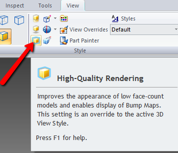
3)  Finally, you must have the High Quality Rendering command enabled.  This command can also be found in the View tab and in the Solids Group: 

Without these options enabled, you are unable to see bump maps and textures that are applied to the model. 

Nathan Pfeiffer
Application Engineer
Ally PLM Solutions, Inc.

Want more tips? Sign up HERE to receive our Tip of the Week.

Register for upcoming free Solid Edge webinars or learn more about
Ally PLM Solutions.


Wednesday, March 25, 2015

SPLM License Server installation issue on Windows 2012 R2

I came across an issue today that I thought I would help others out there.  When trying to load the FlexLM software on the NX10 DVD, I first saw an error talking about Java.  I loaded the latest versions of the 32 and 64 bit Java from the Java website.  I then saw an unusual error saying “ZeroGu6: Windows DLL failed to load.”  It turns out that the version of SPLM License Server on the NX10 DVD has an issue loading on Windows Server 2012 R2.  Next, I downloaded the newer version of the SPLM License Server and it worked with no issues.

If you can’t load (SPLMLicenseServer_v7.0.0_win64_setup.exe or lower) FLEXLM on Windows 2012:
  1. Make  sure the latest 64 bit and 32 bit versions of Java are installed.
  2. Download the SPLMLicenseServer_v7.1.1_win64_setup.exe from https://download.industrysoftware.automation.siemens.com/siemens_plm_licensing/Installs/
  3. You will need your WebKey or need to create a WebKey for the Siemens site (email support@allyplm.com if you need help).
I also found a workaround:
  • Right click on SPLMLicenseServer_v7.0.0_win64_setup.exe and select Properties.
  • Select the 'Compatibility' tab
  • Check the box 'Run this program in compatibility mode for:'
  • On the pull down menu, select 'Windows 7'
  • Select 'OK'
  • Run SPLMLicenseServer_v7.0.0_win64_setup.exe
  • Although the workaround has not been tested, it should work as well.
If you have any additional issues, contact support@allyplm.com.

Madison Rye
Application Engineering Manager
Ally PLM Solutions

Tuesday, March 24, 2015

Eskort Makina designs better with Solid Edge

This biscuit and other special-purpose food making machine manufacturer  uses synchronous technology in Solid Edge and reports impressive results. Eskort Makina has improved production quality and reduced costs, decreased design time 45%, increased design quality, reduced manufacturing costs 20% and significantly improved processes for addressing ENCs and local compliance standards.


Try Solid Edge for free

Learn how Solid Edge can save you time on design and development at http://allyplm.com/solidedge/ or sign up for an informative webinar at http://allyplm.com/futureofcad/ 

Friday, March 20, 2015

Tip of the Week March 20


NX Tip of the Week
March 20, 2015


NX - Ordinate Dimensioning in NX Modeling and Reusing it in Drafting

Today I will explain how to create ordinate dimensions within NX Modeling. I will also show how to reuse the dimensions in Drafting.
     
Ordinate Dimensioning in Modeling Application -


Result in Drafting Environment -

  • To get started, make sure the PMI option is turned ON. By default, it is turned OFF


  • Set the Model View to Work:    


  • Under the PMI Ordinate Dimension command, pick Single or Multiple Dimension.

  • With Single Dimension, use Select Origin where you pick any point. This is going to be the origin of the ordinate dimension.

  • I have selected the single dimension option to help pick one hole at a time:


  •  Start by picking the center of the holes and place them one at a time:


  • Now let's look at the Multiple Selection option. With Multiple Dimension, I can pick all the holes at once.

  • Change the option to Multiple Dimension and pick the origin:


  •  Set the Baseline option:


  •  Before I start selecting the holes, the margins need to be defined. Click on the Define Margins command:


  •   


  •  Here are the options I selected for this example:


  •    


  •  Select the bottom left corner point as the origin:


  •    


  •  Follow the same procedure to get a horizontal margin:


  •  Baseline option step:


  •  Select all the holes by clicking on the center point of the circular edge.

  • Result:


  • Save the Model file.


  • Switch to the Drafting application and place the top model view on the sheet:


  • After placing the view, go to View Settings:


  • Make sure to change the settings to From Model View, click Apply:


  • Final Result:


    Navjot Gill 
    Application Engineer
    Ally PLM Solutions, Inc.

    Want more tips? Sign up HERE to receive our Tip of the Week.


    Wednesday, March 18, 2015

    Maintenance Pack 5 for Solid Edge ST7 is now available for download

    We are happy to inform you that Maintenance Pack 5 for Solid Edge ST7 is now available for download on the GTAC FTP server.

    Maintenance Packs are released for CRITICAL items only. Maintenance Packs are available up to a maximum
    of 15 months following the release date of the English version. The release date for Solid Edge ST7 English was
    08/08/14, making the Maintenance Pack cutoff date 11/08/15.

    ST7 Maintenance Packs can be downloaded from:
    https://download.industrysoftware.automation.siemens.com/solid_edge/ST7/Maintenance_Packs/

    A valid WebKey account is needed to access Maintenance Pack downloads. To create a WebKey you need your Customer Sold-To ID and your WebKey Access Code, both found under Solid Edge Help, About. You can create your WebKey account here: https://plmapps.industrysoftware.automation.siemens.com/webkey/


    Maintenance Packs deliver the most current updates and resolution of PRs to your software platform. You can find detailed information regarding the PRs that a Maintenance Pack addresses in the "readme” .txt file found with the MP download.

    The Ally PLM Technical Support Team is available to answer any questions and provide support for all of your needs including Maintenance packs.  

    You can contact the Ally PLM Technical Support Team via email at technical.support@allyplm.com or via phone at (513) 984-0480 Option: 4

    Ben Weisenberger
    Application Engineer
    Ally PLM Solutions

    Electrotherm designs better with Solid Edge

    This global manufacturer of steel plants and electric vehicles easily moved from 2D to 3D design CAD. It  now designes very large assemblies with Solid Edge. The results include 20% reduced design time, assembly drawings created 34% faster, and a 60% drop in human errors.


    Try Solid Edge for free

    Learn how Solid Edge can save you time on design and development at http://allyplm.com/solidedge/ or sign up for an informative webinar at http://allyplm.com/futureofcad/ 

    Friday, March 13, 2015

    Tip of the Week March 13


    NX Tip of the Week
    March 13, 2015

    NX - Placing Text on Curved Surfaces in NX
    NX provides a simple and powerful tool that allows you to place text on a variety of curved surfaces. With your model open, select the Text command from the dropdown shown:


    When the options bar opens up, change the Type to On Face:

    Then select the face of one of your models, then click down onto Select curve to select one of its edges:


    It will then place your text down and you can use the arrows to move around the text. Moving it up and down the curve will even allow it wrap around multiple angles!
    This method should allow you to create wrapping text on your models although if this doesn't work for your particular model, you can contact us at support@allyplm.com and we can offer you assistance.

    Patrick Barton
    Application Engineer
    Ally PLM Solutions, Inc.
    Want more tips? Sign up HERE to receive our Tip of the Week.


    Wednesday, March 11, 2015

    RESQTEC Zumro designs better with Solid Edge


    This company designs award-winning equipment to handle two tasks: rescuing people in accidents and salvaging old aircraft. The company’s use of Solid Edge to design rescue and salvage equipment includes both 3D design and integrated simulation. Results from using Solid Edge include the creation of professional blueprints and assembly manuals, more effective communication/collaboration with suppliers and a new focus on product innovation and continuous improvement.


    Try Solid Edge for free

    Learn how Solid Edge can save you time on design and development at http://allyplm.com/solidedge/ or sign up for an informative webinar at http://allyplm.com/futureofcad/ 

    Friday, March 6, 2015

    Tip of the Week February 27

     NX Tip of the Week
    March 6, 2015


    NX - Moving an Imported Body to the Absolute Origin

    Hello everyone - In this week's Ally PLM Tip of the Week, we will take a look at a couple of methods that we can use to move an imported body that is out in 3D space to the origin which will make it easier to work with.
         
    1)  Import the desired file
    a. Go to File - Import (in this example a Parasolid file):

    2)  Method 1: Using Move Object
         a. Go to the Edit Pulldown menu and select Move Object:

    b. The default movement type in Move Object is dynamic. Select the body:

    c. I want to reference a keypoint on the body where I want the absolute origin to be.  I'm going to turn on "Move Handles Only" to move the orientation handle relative to the geometry.

    d. Notice I can snap to keypoints of the geometry.  This is going to be the point I want to move "From":

    e. Then, turn off "Move Handles Only" to put you back in a move function.  Then I'm going to select the origin of the Datum Coordinate System as my "To" location.  Notice the body moves from the center of the pocket to the origin:

    f. Now the imported body is at my absolute origin:

    3)  Method 2: Using Move Face
    a. Click on Move Face on the Synchronous Modeling Toolbar:

    b. Window select the body to pick up all the faces.

    c. Make sure your Motion type is set to "Point to Point".

    d. Select the center point of the pocket as your "From" point:

    e. Select the origin point of the Datum Coordinate System as your "To" point:

    f. Click OK.  The body is now at the absolute origin:

    In this Ally PLM Tip of the Week, we looked at using Move Object and Move Face to help move an imported body closer to the absolute origin.

    Click HERE to watch a video of this tip:

    Brandon Carter 
    Senior Application Engineer
    Ally PLM Solutions, Inc.


    Wednesday, March 4, 2015

    Montre Exacte designs better with Solid Edge

    High-precision watch manufacturer uses synchronous technology to replace “design by trial-and-error,” presents images derived from modeling data, and eliminates physical prototypes. Business benefits include predictable quality, reduction in customer complaints, and development of new effective sales materials. 


    Learn how

    Try Solid Edge for free

    Learn how Solid Edge can save you time on design and development at http://allyplm.com/solidedge/ or sign up for an informative webinar at http://allyplm.com/futureofcad/ 

    Monday, March 2, 2015

    Now Available - Maintenance Release NX 10.0.1

    Ally PLM is happy to announce that Maintenance Release NX 10.0.1 is now available for download from the Siemens PLM download server. NX 10.0.1 is an accumulation of fixes built for installation on top of Windows 64-Bit, Linux 64-Bit and Mac OS images of NX 10.0.0.

    Select one of the following links to download this maintenance pack or to review the README. Note: a valid WebKey account is required.

          Windows 64-Bit:
           https://download.industrysoftware.automation.siemens.com/unigraphics/maintenance-release/nx10/win64/
       
          Linux 64-Bit:
           https://download.industrysoftware.automation.siemens.com/unigraphics/maintenance-release/nx10/linux64/
       
          Mac OS:
           https://download.industrysoftware.automation.siemens.com/unigraphics/maintenance-release/nx10/macos/

    Please refer to the README file for Maintenance Release installation instructions.

    The Ally PLM Technical Support Team is available to answer any questions and provide support for all of your needs including maintenance releases.  You can contact the Ally PLM Technical Support Team via email at technical.support@allyplm.com or via phone at (513) 984-0480 Option 4.

    Tracy Tijan
    Marketing Director
    Ally PLM Solutions