This Blog has Moved

This blog has moved to www.allyplm.com/blog

To stay up-to-date with the latest news, tips and tricks, product enhancements and maintenance packs for Siemens PLM Software solutions, visit our new site!

For resources for specific products, you can navigate directly to the product resource page:
... and more!

Friday, December 19, 2014

Maintenance Pack 03 for NX 9.0.3 is Now Available

We are pleased to inform you that Maintenance Pack 03 (MP03) for NX 9.0.3 is now available for download from the Siemens PLM download server. NX 9.0.3 MP03 is an accumulationof fixes built for installation on top of        Windows 64-Bit and Linux 64-Bit images of NX 9.0.3.
   
Select one of the following links to download this maintenance pack or to review the README.  Note: A valid WebKey account is required. 
   
Linux 64-bit:
https://download.industrysoftware.automation.siemens.com/unigraphics/maintenance-packs/nx9/linux64/
   
Windows 64-bit:
https://download.industrysoftware.automation.siemens.com/unigraphics/maintenance-packs/nx9/win64/
   
Please refer to the README file for Maintenance Release installation instructions.

The Ally PLM Technical Support Team is available to answer any questions and provide support for all of your    needs including Maintenance packs.  You can contact the Ally PLM Technical Support Team via email at             technical.support@allyplm.com or via phone at (513) 984-0480 Option: 4.

Tip of the Week December 19

 NX Tip of the Week
December 19, 2014

NX - Using Margins in Drafting with NX 9

Hello NX Users - In this week's Ally PLM Tip of the Week, we will take a look at using margins in NX 9 to create dimensions in drafting as well as aligning dimensions so they track together as you move them.

1)  Margin Options/Values

     a. Go to Preferences-Drafting to get to the Drafting Preferences:

       b. Type "margin" in the search: 


      c. Select the line that says Margin - First Offset

    d. Notice the options for First Offset and Spacing:

2) Placing Dimensions to Margins

a. Go to a Linear Dimension

b. Make sure "Place Automatically" is unchecked:

c. Click the points for the dimension

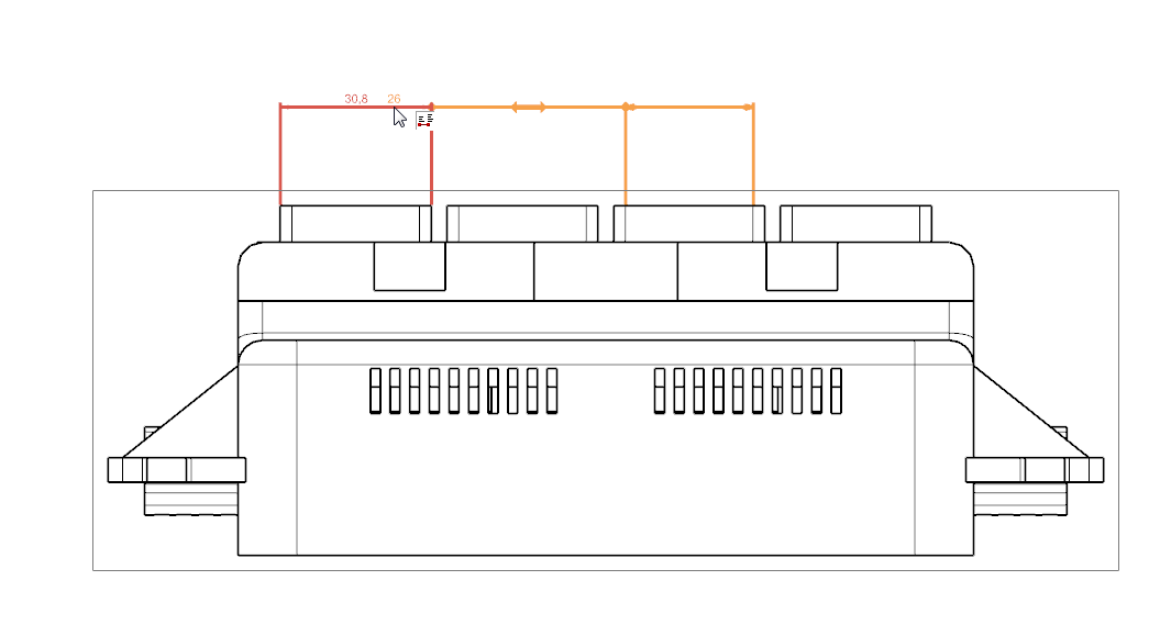
d. Notice as you move your cursor up, the dimension wants to snap to the margins.  The first margin is the first offset (40 mm), every step after that is the spacing offset (10 mm):

e. Create another Linear Dimension

f.  This time make sure "Place Automatically" is on:


g. As soon as the dimension object is selected, the dimension is automatically placed at the first margin (first offset):

3) Create a dimension alignment

          a. Drag the placement dimension to hover over the target dimension.  The target dimension would be the dimension that drives the movement and the placement dimension will track along with it:
          b. This can also be done on creation. While placing the dimension, you can hover over the target dimension to create an alignment:

c. Notice if I move the first dimension, the others track along as well. 

In this Ally PLM Tip of the Week, we looked at using margins to help align and keep dimensions nice and clean in Drafting.  We also looked at how to make dimensions associative, so if one moves the others track along with it.  I hope everyone has a great Holiday Season and a Happy New Year!

Click HERE to watch the video of this demonstration: 

Brandon Carter
Senior Application Engineer
Ally PLM Solutions, Inc.

Want more tips? Sign up HERE to receive our Tip of the Week.
Register for upcoming free NX webinars or learn more about Ally PLM Solutions.

Wednesday, December 17, 2014

Solid Edge ST7 - Maintenance Pack 3 Announcement

Solid Edge ST7 Maintenance Pack 3 for Solid Edge is now available for download.

Maintenance Packs are released for CRITICAL items only. Maintenance Packs are available up to a maximum of 15 months following the release date of the English version. The release date for Solid Edge ST7 English was 08/08/14, making the Maintenance Pack cutoff date 11/08/15.

ST7 Maintenance Packs can be downloaded from:
https://download.industrysoftware.automation.sieme​ns.com/solid_edge/ST7/Maintenance_Packs/

A valid WebKey account is needed to access Maintenance Pack downloads. To create a WebKey you need your Customer Sold-To ID and your WebKey Access Code, both found under Solid Edge Help, About. You can create your WebKey account here: https://plmapps.industrysoftware.automation.siemens.com/webkey/

Ally PLM encourages all of our customers to stay current with released Maintenance Packs. Maintenance Packs deliver the most current updates and resolution of PRs to your software platform. You can find detailed information regarding the PRs that a Maintenance Pack addresses in the "readme” .txt file found with the MP download.

The Ally PLM Technical Support Team is available to answer any questions and provide support for all of your needs; including Maintenance packs.  You can contact the Ally PLM Technical Support Team via email at technical.support@allyplm.com or via phone at (513) 984-0480 Option: 4

Tracy Tijan
Marketing Director
Ally PLM Solutions

Machine tool manufacturer FRÖMAG designs better with Solid Edge


Moving away from its existing 3D CAD system, FRÖMAG quickly embraced the design freedom of synchronous technology in Solid Edge. Results included faster design turnaround, easier and faster implementation of complex designs, and reduced development costs.


Try Solid Edge for free

Learn how Solid Edge can save you time on design and development at http://allyplm.com/solidedge/  or sign up for an informative webinar at http://allyplm.com/futureofcad/   

Tuesday, December 16, 2014

CAMWorks for Solid Edge 2015 Released!


To help you Program Smarter and Machine Faster, there are new features, new modules and better programming.

New Features - Enjoy new features like assigning tools to operations, light rebuilds for turn parts and more.

Better Programming - The user-experience has been given a boost with some additions including tool crib priority options, Tech-DB enhancements and define stock material based default cutting parameters.

New Add-On Module - Reduce your setup time with CAMWorks for Solid Edge Virtual Machine. Virtual Machine provides true G-code verification, the first end-to-end integration from CAD to CAM to verification and on to the machine controller.

CAMWorks for Solid Edge is compatible with Solid Edge ST7 and only available in 64-bit.

Click HERE for an overview of the key enhancements:


New feature and enhancement details are available in the Downloads Area (login required) of the website:

Special Note: Because this release has taken longer to deliver than expected and as a token of appreciation for being a valued customer, your current annual subscription program is being extended by six months!

Click HERE to learn more about CAMWorks for Solid Edge and how to apply it to your everyday work operations.

Request a quote for CAMWorks for Solid Edge.

Tracy Tijan
Marketing Director
Ally PLM Solutions

Friday, December 12, 2014

Tip of the Week December 12


NX Tip of the Week
December 12, 2014

NX - Using Visualization Tools to Analyze Your IPW in NX CAM

There are visualization tools in NX CAM that can really help you visualize the In Process Workpiece (IPW) while you are creating machining operations. It is very important to know exactly how much material is left on your part when selecting the next tool and operation in the machining sequence. Using "Show Thickness by Color" and "Clip Section" can greatly enhance your capability to analyze the IPW. Here are some steps to use these functions along with some examples of where they may be beneficial.

1)  Use Verify and 3D Dynamic to display the IPW:

2) Use Show Thickness by Color to display the IPW. The different colors show the different amounts of material left on the part:

3) While in the Thickness by Color dialog you can select various points on the IPW by simply left-clicking on the IPW in the graphics window.The value shown is the amount of material left at that particular location:

4) Use Clip Section to slice the model and IPW to better visualize areas that are difficult to see:

5) Move the Manipulator to the center of a hole to check hole depths and diameters:

Chad Varney
Application Engineer
Ally PLM Solutions, Inc.

Want more tips? Sign up HERE to receive our Tip of the Week.


Register for upcoming free NX webinars or learn more about Ally PLM Solutions.

Wednesday, December 10, 2014

Sailboat manufacturer eliminates physical mockups, saves 2 months development time

Wauquiez International designs better with Solid Edge. The company manufactures comfortable, fast and reliable sailboats for deep-sea cruising. Other benefits provided by the use of Solid Edge included getting boats to buyers sooner with faster design cycles and the use of virtual mockups to sell new boat concepts.
 

Learn how
http://www.plm.automation.siemens.com/en_us/about_us/success/case_study.cfm?Component=214289&ComponentTemplate=1481

Try Solid Edge for free

Friday, December 5, 2014

Medical device maker achieves 100 percent SolidWorks to Solid Edge data move; avoids modeling kernel change concerns

Helena Laboratories designs better with Solid Edge. The laboratory instrument maker documented multiple benefits in the move to Solid Edge and its synchronous technology. That included reductions in design and edit time, elimination of difficult history-based feature design processes, ability to leverage creativity and experience of design team veteran engineers, and the import and easy conversion of valuable wireframe designs.
(Watch the video and read the story)


Try Solid Edge for free

Tip of the Week December 5


Solid Edge Tip of the Week
December 5, 2014


Solid Edge - Reading the ST6 Holes.txt into ST7

There is a Hole Database Converter.exe you can run to add the old Holes.txt to the Excel sheets for ST7. 

1) Go to C:\Program Files\Solid Edge ST7\Custom\HoleDatabaseConverter\bin
 
2) Run the Hole Database Converter.exe
 
3) Select the Add button and select the old Holes.txt from ST6
 
4) Select Convert and the holes will be added to ST7 
 
The purpose of this exercise is to convert Holes.txt files to the .xlsx format

Navjot Gill
Application Engineer
Ally PLM Solutions, Inc.

Want more tips? Sign up HERE to receive our Tip of the Week.


Register for upcoming free Solid Edge webinars or learn more about Ally PLM Solutions. 

Monday, November 24, 2014

Tip of the Week November 21

NX Tip of the Week
November 21, 2014

NX - Hiding WCS and DCS in NX 8.5 and NX 9.0

1) There are two different ways you can hide WCS in a modeling environment. 

a. In NX 8.5, select Format > WCS > Display:

With NX 9.0, select Menu > Format > WCS > Display:

  b) Or, with NX 8.5 and NX 9.0, press W on the keyboard, toggle the display of the WCS.


2) There are different ways you can turn off the Datum Coordinate system in a modeling environment.

 a.  With both NX 8.5 and NX 9.0, hold the Control key down and press W (Ctrl + W). Click on the (-) sign for the Coordinate System row: 


b.  Or, with NX 8.5, select Format > Layer Visible in View:

With NX 9.0, select Format > Layer Visible in View:     

Then highlight the view and click OK:      


Using QuickPick, highlight the Coordinate System. Be sure to pick the Datum Coordinate System, this will automatically highlight the layer which contains the entity:   

Click on Invisible > OK:   

Navjot Gill
Application Engineer
Ally PLM Solutions, Inc.

Want more tips? Sign up HERE to receive our Tip of the Week.


Register for upcoming free NX webinars or learn more about Ally PLM Solutions.


Wednesday, November 19, 2014

Grinding machine manufacturer cuts design time in half

Supertec designs better with Solid Edge. Synchronous technology helps cut design time but also reduces errors up to 20 percent. "With Solid Edge, customer review meetings usually take about 20 minutes, which is really a great improvement from the previous one-day process," says Zhu Yaru, sales associate with Supertec.


Try Solid Edge for free

A Whole New Experience with the 3Dconnexion 3D Mouse

Your 3D mouse just got better! You can now customize your 3Dconnexion 3D mouse for optimum performance. Tailor the settings and buttons to meet your own needs!

Click HERE to find out more about advanced features, maximizing your mouse's power and customizing more than one mouse for your team.


Learn the benefits of a 3D Mouse:

Friday, November 14, 2014

Tip of the Week November 14


Solid Edge Tip of the Week
November 14, 2014

Solid Edge - Assembly Tips

A great command inside the Assembly environment is the Capture Fit command.  This command can be used to capture the assembly relationship and faces used to position a part or subassembly already placed in an assembly. You can then place the part or subassembly again using fewer steps. The steps to use the Capture Fit command are as follows: 

1) In the assembly window, select a part for which you want to capture relationships.

2) Choose Home tab -> Relate Group -> Capture Fit
3) In the Capture Fit dialog box, use the Add and Remove buttons to specify which relationships you want to capture and then click OK. 

The Capture Fit command is perfect when used with hardware such as bolts or other commonly used parts. After having Solid Edge learn the assembly relationships, when you drop the part into the assembly, the faces of the placement part highlight and you are prompted to select the corresponding faces on the target part. This allows you to fully place a part in half the clicks as normal.

Another tip when creating relationships between parts in an assembly is to hold "R" and click on a part to show its reference planes. This is a great tip that saves you from having to right click on a part and click on Show/Hide Component to turn the reference planes on and off. To use this shortcut you must select an element on the placement part, then you can hold down the "R" key and select the part you plan to align the placement part to. This will turn on the reference planes of that part. You can then create the relationship between the parts and when you finish the command, the reference planes will turn off again.  

Ben Weisenberger
Application Engineer
Ally PLM Solutions, Inc.

Want more tips? Sign up HERE to receive our Tip of the Week.


Register for upcoming free Solid Edge webinars or learn more about Ally PLM Solutions.

Wednesday, November 12, 2014

Screw and cylinder manufacturer reduces design change time from 8 to 2 hours

Tan Star designs better with Solid Edge. Results from the use of Solid Edge included reduced design change time from a day to 2 hours, identification and correction design errors quickly and the use of 3D models to enhance marketing and overall profitability.


Learn how

Try Solid Edge for free

Tuesday, November 11, 2014

Solid Edge ST7 - Maintenance Pack 2 Announcement

Solid Edge ST7 Maintenance Pack 2 for Solid Edge is now available for download.

Maintenance Packs are released for CRITICAL items only. Maintenance Packs are available up to a maximum of 15 months following the release date of the English version. The release date for Solid Edge ST7 English was 08/08/14, making the Maintenance Pack cutoff date 11/08/15.

ST7 Maintenance Packs can be downloaded from:   https://download.industrysoftware.automation.sieme​ns.com/solid_edge/ST7/Maintenance_Packs/

There were Solid Edge Embedded Client policy file updates in MP2. It’s vitally important that you install SEEC
Administrator, which delivers the policy files to TC_DATA.

Maintenance Pack Executables (.exe files) patch existing product dlls. Maintenance Pack executables
are all inclusive and can be installed on top of a base release or any released Maintenance Pack.

Maintenance Pack Installs (.zip files) are complete product setups. Therefore, existing versions must be
uninstalled using Add/Remove Programs from the Control Panel prior to installing the new setup.
This Maintenance Pack addresses the following PRs:

===API===
PR 1997747: Solid Edge crashes with our add-in if a drawing has balloons
PR 1128963: Custom add-in command is removed from Quick Access Toolbar when Solid Edge is restarted
PR 1991583: QueryByName doesn't return a result for the "Default" Attribute Set
PR 1999928: API RevManager LinkedDocuments changed behavior in ST7
PR 1997369: No lines in DXF file when using the API Method .SaveAsFlatDXFEx()
PR 1998444: Abort trying to get access to material Table via API
PR 1994706: SePvAdp.exe doesn't create a jt-file from an assembly and exit with error
PR 7224772: Old material library APIs do not work for a single material library
PR 7216470: Add a property to not resolve links for SEReader
PR 7214771: SEReader reporting original filenames after a rename
Note: The new SEReader.dll and map files are posted on the GTAC FTP server:
                https://download.industrysoftware.automation.sieme​ns.com/solid_edge/ST7/Maintenance_Packs/MP02/

===Draft===
PR 1997706: Can't locate elements of different type to connect to
PR 7196026: Abort getting physical properties in some cases
PR 1128251: Duplicate dimensions in a lot of drafts
PR 2247261: Parallel dimensions are abnormal
PR 1999206: Can't specify a Parts list through a Display Configuration view anymore
PR 1999705: Parts List will not allow user defined rows to be added
PR 7201475: Solid Edge crashed when performing retrieve dimensions from dft
PR 2248233:The placement of dimensions changes
PR 7212537:Edit list changes when Solid Edge Options are modified
PR 1921943: locked dimension changes value when geometry dragged
              
===Part/Profile/Sheet Metal===
PR 1127865: KeyShot 5 is not running with a Solid Edge Classic borrowed license
PR 1997489: Flat Pattern does no longer work in ST7 but was OK in ST6, regression
PR 1127777: Adding custom property of 'Text' type to a material causes crash/doesn't work
PR 1973206: Split Body causes the bodies to rearrange
PR 1997728: Wrong material , when using create Part in Place
PR 2247477: Code change made due to investigation of SE Crashlog
PR 2249018: FOP master file has lost FOP Tab.
PR 7219732: Cannot create a sweep from a 3D sketch
PR 2248871: non-reproducible abort during file close
PR 7177036: Export JT from SE with Model view is defined incorrectly
PR 7219285: ST7 Distance command doesn't find center points
PR 7196340: Fixed a problem with Filename being truncated when translating to DWG

===Insight===
PR 1990496: Edit Profile (Upload) pops up since ST5MP11 even the part haven't been changed
PR 1985438: File not found message when SE tries to open a renamed FOA, RevMan open OK
PR 8250895: Revision Manager crash when opening files from Insight DocLibs

===Insight Connect===
PR 7206624: Labels missing for some commands when localized
PR 2248073 : It is impossible to do a "Replace Part with Standard Part" in an Insight Managed

===Solid Edge SP, Server, Standalone Client, Solid Edge Client===
PR 7166961: Add to Library is putting files in wrong location
PR 1996701: Part Title not mapped to Item Title
PR 1128234: Element.Titel (Item.Title) and Teil.Titel (Part.Title) not correct
PR 7199708: Delay observed in loading toolbars for drawing with no write access

===Solid Edge Embedded Client===
PR 7188611: places linked drawing in wrong location in BOM
PR 7195451: Save As on Assembly assigns Draft to unique Item ID
PR 1991419: Different LOV displayed in Solid Edge compared to Teamcenter
PR 1129164: SE Crashes, when saving a Part file, where a feature is pasted in
PR 8250101: can't copy sync sketch
PR 1128098: Poor performances when creating, saving, or revising a document
PR 1998410: Column "Project ID" disappears, if SEEC is working with SSO/TcCS
PR 7155782: Save As fails when Insert Part Copy used with TC10.1
PR 7225135: Revise creates wrong dataset name when specific custom property exists
PR 7222814: Save As on Draft creates link to original Part instead of new Part

Ben Weisenberger
Application Engineer
Ally PLM Solutions

Thursday, November 6, 2014

Just Announced - Solid Edge University 2015 in Cincinnati!

Save the Date for Solid Edge University 2015
Cincinnati, Ohio
October 26th-28th, 2015


This is a can't miss event for new and experienced Solid Edgers!

Join us for 2 days of basic and advanced Solid Edge curriculum including a Developer Day and Design Management Workshop. More than 80 technical and hands-on training sessions will be delivered by the Solid Edge team and expert users. 
Learn why you should attend Solid Edge University 2015:

More details to follow at the Solid Edge University 2015 website.

Tracy Tijan
Marketing Director
Ally PLM Solutions

Wednesday, November 5, 2014

To all GM suppliers who use 2-tier connections to GM Teamcenter databases

If you experience a Teamcenter license issue in connecting to the GM database after November 1st, please go the GTAC website and download your latest archived Siemens PLM license file. A temporary 90-day work-around has been provided to resolve a problem with unwanted messages and possibly incorrectly denied access to some Teamcenter functionality.

Please install this license file as soon as possible.

Learn more at http://allyplm.com/knowledgebase/2014/11/5/are-you-a-gm-supplier-experiencing-a-teamcenter-license-issue

Madison Rye
Application Engineering Manager
Ally PLM Solutions, Inc

Contract manufacturer cuts design time in half; reduces manufacturing cycle 15%


UWC Holdings designs better with Solid Edge. Results included reducing design time from 4 weeks to 2 weeks, increased efficiency across operations, including virtually eliminating errors from imported data, saving significant time in working with large assemblies and substantially increasing the use of existing data for new projects. Taking advantage of synchronous technology, a tool that supports bulk data migration across platforms, UWC has realized a 15 percent faster production rate, something that UWC engineers say was not possible prior to using Solid Edge.


Try Solid Edge for free

Friday, October 31, 2014

Tip of the Week October 31


NX Tip of the Week
October 31, 2014

NX - Changing Feeds and Speeds in Multiple Operations in NX CAM

In NX CAM, you can change Feeds and Speeds in multiple operations at the same time.  An example may be if you have 10 milling operations using the same cutter and you have your part programmed with Feeds and Speeds set for cutting Aluminum but then you want to use those same operations on a part made from Mild Steel.  Instead of opening each individual operation to change the Feeds and Speeds values, you can do this all at once by using Object > Feed Rates.  Below is an example of changing multiple Spot Drilling operations that did not have any Feeds and Speeds values generated.

1) Select all of the operations that you want to change:


2) Right click and select "Object > Fee Rates":


3) In the Feeds and Speeds dialog, enter the desired Speed and Feed values and click "OK":


4) Now notice that each operation has been changed according to the values that were entered:


Chad Varney
Application Engineer
Ally PLM Solutions, Inc.

Want more tips? Sign up HERE to receive our Tip of the Week.
Register for upcoming free NX webinars or learn more about Ally PLM Solutions.