This Blog has Moved

This blog has moved to www.allyplm.com/blog

To stay up-to-date with the latest news, tips and tricks, product enhancements and maintenance packs for Siemens PLM Software solutions, visit our new site!

For resources for specific products, you can navigate directly to the product resource page:
... and more!
Showing posts with label Tip of the Week. Show all posts

Friday, December 4, 2015

NX Tip of the Week December 4


NX Tip of the Week
December 4, 2015

NX - Exporting to a Spreadsheet from Navigator 

Hello everyone,

In this week's Ally PLM Tip of the Week, we will take a look at a how to export content from the Assembly Navigator.  In any navigator window, we can configure the content that shows up in the columns.  Once these columns are configured, we can easily export this information to a spreadsheet for capture.

Here is a short video that demonstrates this tip:


Thank you,
Brandon Carter
Senior Application Engineer
Ally PLM Solutions, Inc.


Want more tips? Sign up HERE to receive our Tip of the Week. 
Register for upcoming free NX webinars or learn more about Ally PLM Solutions.

Friday, November 20, 2015

NX Tip of the Week November 20


NX Tip of the Week
November 20, 2015

NX - Editing the Post Processor in NX CAM

In NX CAM, you can edit the standard post processor list enabling you to add your own post processors to the list. You can also reorder the list according to the posts you use most frequently. This can be very useful because this keeps you from having to browse to a certain post that wasn't in the list when your software was installed.  

Here is a short video that shows the standard post list, adding a post to the list, deleting posts from the list, and re-ordering the post list:


Thank you,

Chad Varney
Application Engineer
Ally PLM Solutions, Inc


Want more tips? Sign up HERE to receive our Tip of the Week.


Register for upcoming free NX webinars or learn more about Ally PLM Solutions.

Friday, November 13, 2015

Solid Edge Tip of the Week November 13


Solid Edge Tip of the Week
November 13, 2015

Solid Edge - Document Name Enhancements
A lot of times, the information provided to you in the pathfinder can be lacking:


This can be improved with the document name formula in the Solid Edge options:


Clicking Change brings up the Document Name Formula pop-up:


Here you can add text before or after the [Filename] including other properties of that part file:


You can add properties like the material, project name, author and many other properties making a glance at the pathfinder much more informative:


I hope you found this information useful!

Thanks,
Navjot Gill
Application Engineer
Ally PLM Solutions, Inc.

Want more tips? Sign up HERE to receive our Tip of the Week. 


Register for upcoming free Solid Edge webinars or learn more about Ally PLM Solutions.


Friday, November 6, 2015

Solid Edge Tip of the Week November 6

Solid Edge Tip of the Week
November 6, 2015

Solid Edge - Turning on the List of Blocks in Solid Edge Draft

In this Ally PLM Tip of the Week, we are going to look at the option to display existing blocks on a Solid Edge drawing. If you are not familiar with blocks, they are groups of 2D geometry. Native 2D geometry can be blocked within Solid Edge draft or blocks from .dwg can be read into Solid Edge. 

1) Open a drawing that has blocks. This may be a native Solid Edge file or something opened from AutoCAD:

Blocks:

2) Over in the Library tab, toggle on the "Show Blocks" command:  

3) Notice the Block names will be listed under Active Document:

4) We can also select blocks from other drawings and use them in our active document. Select a dft/dwg from the folder above. Notice the preview of the block in the lower window.  CB Network protect is a block on the Circuit Protectors.dft file:

5) Drag and drop the block into the active drawing: 

6) We can create our own blocks using the block command. To find out more information on the Block command, search the Help or click F1 on the keyboard once in the Block command: 


7) There are sample blocks/block libraries delivered in the installation directory of Solid Edge here:  C:\Program Files\Solid Edge ST?\Sample Blocks:

In this week's Tip of the Week, we looked at how to display blocks in active and selected documents. For more information, check out our Ally PLM Lunch Bytes session on 2D Diagramming and Schematics: http://solidedgevideos.blogspot.com/2012/09/solid-edge-diagrams-and-schematics.html

Brandon Carter
Senior Application Engineer
Ally PLM Solutions, Inc.

Want more tips? Sign up HERE to receive our Tip of the Week.

Register for upcoming free Solid Edge webinars or learn more about Ally PLM Solutions.

Friday, October 16, 2015

NX Tip of the Week October 16

NX Tip of the Week
October 16, 2015

NX - Using the In Process Workpiece for
Multiple Setups in NX CAM

You can use the In Process Workpiece (IPW) for multiple setups in NX CAM making programming easier and more efficient.  Using the IPW as Blank Geometry can help you visualize the material that has already been cut and also allow NX to create very efficient operations without excessive tool path motion.  The steps below will show the process for using the IPW in a part that requires multiple setups.

1)  The part starts out with the blank defined using a bounding block:

2)  After the operations on the first setup have completed the IPW looks like this:

3)  Now I will use the IPW option to define the blank for the second setup:

4)  Select Source for IPW:

5)  Use the WORKPIECE from the first setup:

6)  Use the Update button to load the IPW from the first setup:

7)  Notice the IPW displays with the operations from the first setup complete:

8)  This shows the second setup operations have been completed and now the IPW is ready for the third setup:


Thank you,
Chad Varney
Application Engineer
Ally PLM Solutions, Inc.

Want more tips? Sign up HERE to receive our Tip of the Week.

Register for upcoming free NX webinars or learn more about Ally PLM Solutions.

Friday, October 9, 2015

NX Tip of the Week October 9


NX Tip of the Week
October 9, 2015

NX - Surfacing Tools

Hello everyone - In this week's Ally PLM Tip of the Week, we will take a look at a few different surfacing tools within NX.  I'm defining surfacing tools as any tool required to get more than just a simple shape; more than just extrude or revolve.  The underlying curves are what give the surface definition.  The surface is only as good as the underlying curves.  You may have asked yourself, which surfacing command should I use to create my desired shape?  For example, if we are trying to loft a shape from section to section, you may be trying to determine the difference between Through Curves and Through Curves Mesh.  We will look at the requirements for some of these commands as well as some of the options.  All of these commands have the option to create a solid or sheet (surface) in the settings. 

When defining a surface we look at something called U and V lines.  U and V lines are the definitions for a surface.  Imagine you take a surface and mesh it.  The lines in one direction will be U direction and the lines perpendicular to the U lines will be V lines.

Typically, when we are defining the curves to create our surface, sections will be in one direction (U direction) and the cross curves will be in the other direction (V direction), for example.

Let's take a look at some of these commands:
1) Ruled Surface
Ruled surface requires two sections and only two sections.  The result uses a lofting technique from one section to the other.

2) Through Curves 

Through Curves requires a minimum of two sections, but can have more than two.  This is a lofting technique that can do more than two sections.

3) Through Curves Mesh 

Through Curves Mesh requires a minimum of two sections, but can have more than two.  It also requires a minimum of two cross curves, but can have more than two.  Cross curves are typically defined in the perpendicular direction to the section inputs.  This technique lofts from section to section and applies the cross curve definitions in the other direction.  The cross curves must be connected to the sections.

4) Studio Surface 

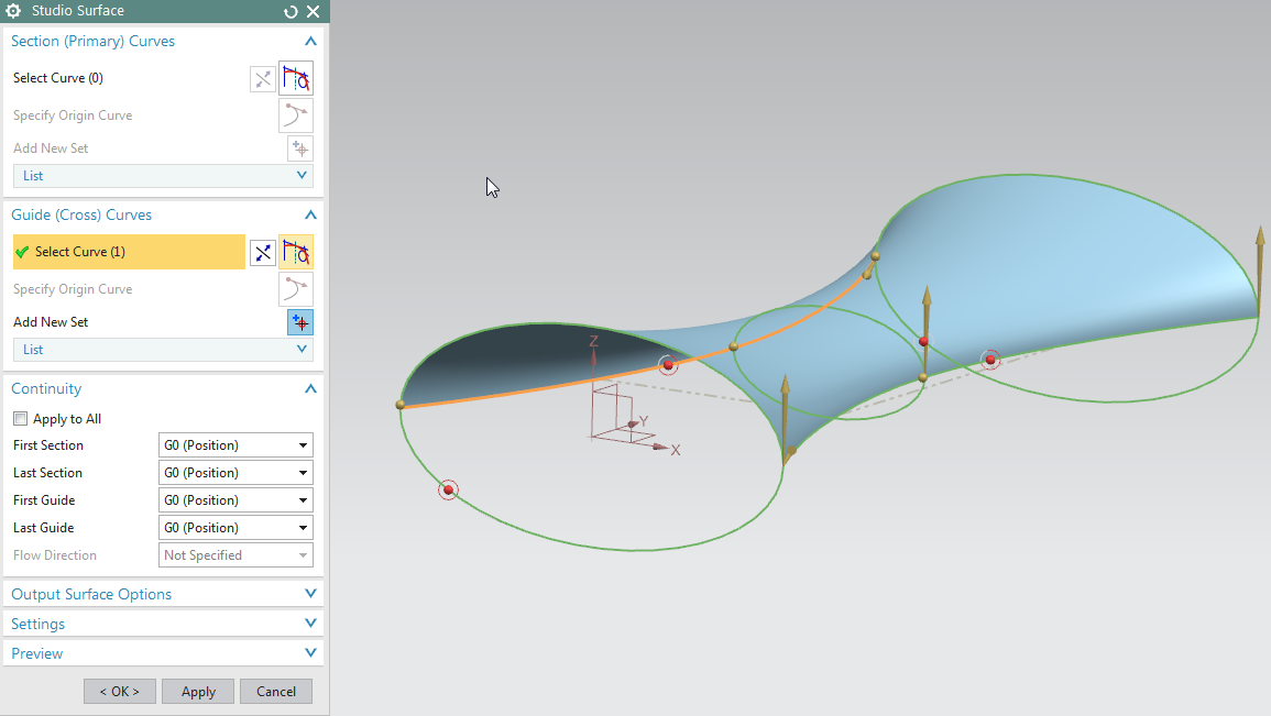
Studio Surface is similar to Through Curves Mesh as far as definition.  It produces swept for lofted features from a network of section strings, or a network of section strings and up to three guide strings.  It requires at least two inputs.  It can be two sections or one section and one guide/cross curve at minimum.  Studio Surface also has some other options for flexibility within the feature.  Studio Surface can create lofted shapes or swept shapes within the same command. Studio Surface also previews as soon at two inputs are defined.  The cross curves do not have to be connected to the cross sections to get a result.  

Studio Surface has an option called "Switch Strings" which can toggle your U and V line definition curves: 

5) Sweep Along Guide 

Sweep Along Guide requires one section and one guide curve.  It takes the section and sweeps it down the guide definition.

6) Tube 

Tube just needs a path definition.  The cross section is determined to be circular with tube parameters included.

7) Swept

Swept takes a cross section definition and sweeps it along a path.  It can have multiple sections but only up to three guide strings.  In the screen shot below, the section and guide curve is not connected.  They do not need to be connected for the swept algorithm.

8) Variational Sweep 

Variational Sweep takes a profile and sweeps it between two curves or surface edges.  Because it is a sweep, the sketch section is created with the on path option.  How the sketch is connected to the surface edges/curves determines its sweep path.  It varies as it transitions between the input curves.  You can sweep faces that are coincident, tangent, or normal to other curves and faces, add secondary sections to vary dimensions at specific locations, or extend the body beyond the length of the path or limit it.

In this Ally PLM Tip of the Week, we took a look at some of the requirements for the different surfacing tools.  This information can help you pick the proper feature for your desired surface requirement.

Brandon Carter
Senior Application Engineer
Ally PLM Solutions, Inc.

Want more tips? Sign up HERE to receive our Tip of the Week. 

Register for upcoming free NX webinars or learn more about Ally PLM Solutions.


Friday, October 2, 2015

Solid Edge Tip of the Week October 2


Solid Edge Tip of the Week
October 2, 2015

Solid Edge - Feature Library

In this week's tip, we will be taking a closer look at the Solid Edge Feature Library.  Not only can the feature library be used to pull in completed parts but also previously created features in Solid Edge.  This is especially useful to help reduce design time when frequently using the same features.

A feature library entry may contain any of the following synchronous elements:
  • Features
  • Faces
  • Sketches
  • Planes
  • Coordinate systems
  • Constructions
**Note:  You can only place a synchronous feature library member while in the synchronous environment.

You can add to the feature library from the Ordered environment.  The only ordered element you can add is a feature.  When placing an ordered feature in the feature library, the attributes for the feature are maintained.

A feature library entry cannot contain a mixture of synchronous and ordered elements.

**Note:  You can only place an ordered feature library member while in the ordered environment.

For Ordered:

1)  With the part model open, on the left side of the screen you will see the feature library tab.  Open this and create a Feature Library folder:

2)  In the Pathfinder for your model hover over the feature you wish to copy into the feature library to quickly reuse in future models and select "Copy": 

3)  Now, once again in the feature library tab, select paste to put this feature in your feature library folder: 

4)  Upon pasting you will notice that the Feature Set Information dialog box is displayed.  You can use the Feature Set Information dialog box to review the feature elements which were captured, review their status, and define custom prompts and notes for when you later place the library member.

Notice in the picture below that there are three elements indented under the Cutout 1 row: a Profile Plane and two Dimensions. Also, notice the Status column. When you later place the library member, you must define a planar face or reference plane because its status is listed as Required. The two Dimensions have a status of Optional. When you later place the library member, you can define new edges for the dimensions or you can skip them, and define the edges later:

5)  To pull the created feature into a new part, open the Feature library and drag the feature you created previously into the graphic window. 

6)  Notice after dragging in the feature that the first row in the Feature Set Information dialog box is active, which requires that you define a profile plane. 


7)  After selecting the appropriate plane, you will notice that the Status in the Feature Set Information dialog box is now changed to "Defined".   You can now do the same thing with your dimensions.  After doing this, these, too, will be "Defined":   


8)  Once these have been defined you will notice the feature you saved to the Feature library is now present on your model.  This has saved a lot of design time by not needing to recreate the cutout you used on another model.

For Synchronous Modeling:
Synchronous Modeling does not require the use of the Feature Set Information Dialog box. Saving your feature follows the same steps as Ordered Modeling but placing it is slightly different.  In Synchronous, you drag in the feature then locate it using the Steering Wheel.  The feature is not placed until you have clicked in the appropriate location.

I hope you found this information helpful!

Thanks,
Nathan Pfeiffer
Application Engineer
Ally PLM Solutions, Inc. 

Want more tips? Sign up HERE to receive our Tip of the Week.