This Blog has Moved

This blog has moved to www.allyplm.com/blog

To stay up-to-date with the latest news, tips and tricks, product enhancements and maintenance packs for Siemens PLM Software solutions, visit our new site!

For resources for specific products, you can navigate directly to the product resource page:
... and more!
Showing posts with label Siemens PLM Software. Show all posts

Friday, December 4, 2015

NX Tip of the Week December 4


NX Tip of the Week
December 4, 2015

NX - Exporting to a Spreadsheet from Navigator 

Hello everyone,

In this week's Ally PLM Tip of the Week, we will take a look at a how to export content from the Assembly Navigator.  In any navigator window, we can configure the content that shows up in the columns.  Once these columns are configured, we can easily export this information to a spreadsheet for capture.

Here is a short video that demonstrates this tip:


Thank you,
Brandon Carter
Senior Application Engineer
Ally PLM Solutions, Inc.


Want more tips? Sign up HERE to receive our Tip of the Week. 
Register for upcoming free NX webinars or learn more about Ally PLM Solutions.

Friday, November 20, 2015

NX Tip of the Week November 20


NX Tip of the Week
November 20, 2015

NX - Editing the Post Processor in NX CAM

In NX CAM, you can edit the standard post processor list enabling you to add your own post processors to the list. You can also reorder the list according to the posts you use most frequently. This can be very useful because this keeps you from having to browse to a certain post that wasn't in the list when your software was installed.  

Here is a short video that shows the standard post list, adding a post to the list, deleting posts from the list, and re-ordering the post list:


Thank you,

Chad Varney
Application Engineer
Ally PLM Solutions, Inc


Want more tips? Sign up HERE to receive our Tip of the Week.


Register for upcoming free NX webinars or learn more about Ally PLM Solutions.

Wednesday, November 4, 2015

What's New in Teamcenter 11!

The new release of Teamcenter 11 has tons of new enhancements to help you significantly increase your return-on-investment. New features include:

  • New self-service administrative tools enabling suppliers to obtain data without help from OEMs
  • Additional features allowing for better integration with the product development process
  • A new administration data documentation report tool making it easier to facilitate your Teamcenter deployments

Learn more with What's New in Teamcenter 11.2

Friday, October 16, 2015

NX Tip of the Week October 16

NX Tip of the Week
October 16, 2015

NX - Using the In Process Workpiece for
Multiple Setups in NX CAM

You can use the In Process Workpiece (IPW) for multiple setups in NX CAM making programming easier and more efficient.  Using the IPW as Blank Geometry can help you visualize the material that has already been cut and also allow NX to create very efficient operations without excessive tool path motion.  The steps below will show the process for using the IPW in a part that requires multiple setups.

1)  The part starts out with the blank defined using a bounding block:

2)  After the operations on the first setup have completed the IPW looks like this:

3)  Now I will use the IPW option to define the blank for the second setup:

4)  Select Source for IPW:

5)  Use the WORKPIECE from the first setup:

6)  Use the Update button to load the IPW from the first setup:

7)  Notice the IPW displays with the operations from the first setup complete:

8)  This shows the second setup operations have been completed and now the IPW is ready for the third setup:


Thank you,
Chad Varney
Application Engineer
Ally PLM Solutions, Inc.

Want more tips? Sign up HERE to receive our Tip of the Week.

Register for upcoming free NX webinars or learn more about Ally PLM Solutions.

Friday, October 9, 2015

NX Tip of the Week October 9


NX Tip of the Week
October 9, 2015

NX - Surfacing Tools

Hello everyone - In this week's Ally PLM Tip of the Week, we will take a look at a few different surfacing tools within NX.  I'm defining surfacing tools as any tool required to get more than just a simple shape; more than just extrude or revolve.  The underlying curves are what give the surface definition.  The surface is only as good as the underlying curves.  You may have asked yourself, which surfacing command should I use to create my desired shape?  For example, if we are trying to loft a shape from section to section, you may be trying to determine the difference between Through Curves and Through Curves Mesh.  We will look at the requirements for some of these commands as well as some of the options.  All of these commands have the option to create a solid or sheet (surface) in the settings. 

When defining a surface we look at something called U and V lines.  U and V lines are the definitions for a surface.  Imagine you take a surface and mesh it.  The lines in one direction will be U direction and the lines perpendicular to the U lines will be V lines.

Typically, when we are defining the curves to create our surface, sections will be in one direction (U direction) and the cross curves will be in the other direction (V direction), for example.

Let's take a look at some of these commands:
1) Ruled Surface
Ruled surface requires two sections and only two sections.  The result uses a lofting technique from one section to the other.

2) Through Curves 

Through Curves requires a minimum of two sections, but can have more than two.  This is a lofting technique that can do more than two sections.

3) Through Curves Mesh 

Through Curves Mesh requires a minimum of two sections, but can have more than two.  It also requires a minimum of two cross curves, but can have more than two.  Cross curves are typically defined in the perpendicular direction to the section inputs.  This technique lofts from section to section and applies the cross curve definitions in the other direction.  The cross curves must be connected to the sections.

4) Studio Surface 

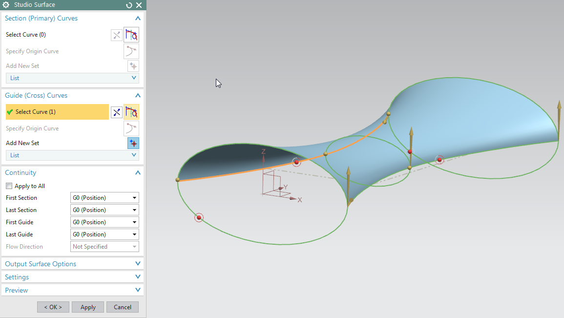
Studio Surface is similar to Through Curves Mesh as far as definition.  It produces swept for lofted features from a network of section strings, or a network of section strings and up to three guide strings.  It requires at least two inputs.  It can be two sections or one section and one guide/cross curve at minimum.  Studio Surface also has some other options for flexibility within the feature.  Studio Surface can create lofted shapes or swept shapes within the same command. Studio Surface also previews as soon at two inputs are defined.  The cross curves do not have to be connected to the cross sections to get a result.  

Studio Surface has an option called "Switch Strings" which can toggle your U and V line definition curves: 

5) Sweep Along Guide 

Sweep Along Guide requires one section and one guide curve.  It takes the section and sweeps it down the guide definition.

6) Tube 

Tube just needs a path definition.  The cross section is determined to be circular with tube parameters included.

7) Swept

Swept takes a cross section definition and sweeps it along a path.  It can have multiple sections but only up to three guide strings.  In the screen shot below, the section and guide curve is not connected.  They do not need to be connected for the swept algorithm.

8) Variational Sweep 

Variational Sweep takes a profile and sweeps it between two curves or surface edges.  Because it is a sweep, the sketch section is created with the on path option.  How the sketch is connected to the surface edges/curves determines its sweep path.  It varies as it transitions between the input curves.  You can sweep faces that are coincident, tangent, or normal to other curves and faces, add secondary sections to vary dimensions at specific locations, or extend the body beyond the length of the path or limit it.

In this Ally PLM Tip of the Week, we took a look at some of the requirements for the different surfacing tools.  This information can help you pick the proper feature for your desired surface requirement.

Brandon Carter
Senior Application Engineer
Ally PLM Solutions, Inc.

Want more tips? Sign up HERE to receive our Tip of the Week. 

Register for upcoming free NX webinars or learn more about Ally PLM Solutions.


Friday, August 28, 2015

NX Tip of the Week August 28


NX Tip of the Week
August 28, 2015

NX - Snap to Object
When modeling in NX there are many times where we want to extend a shape to another shape.  For example when using "Pull Face" in Synchronous Modeling, we want to pull a face to be parallel with another existing face on the model.  Of course, we can measure the distance between the 2 faces and input that value into the dialog.  However, there is a shortcut that can save you time and avoid the possibility of accidentally inputting an incorrect value.  The steps below will show how to use "Snap to Object" in the Extrude command when creating blank stock to be used in NX CAM.  Keep in mind that "Snap to Object" is available in multiple commands in NX.
1)  This is the part that I will be programming using NX CAM. In modeling, I will create a blank shape representing the raw material:
2)  Within the Extrude command, I have started the extrude 1.5" from the back of the part:


3)  Since I want the extrude to extend to the front face of the part I will use "Snap to Object" by right clicking on the blue arrow:


4)  Then I will simply pick the face I want to extend to:


5)  As you can see, the extrude is now extended to 5.6" which is parallel to the face of the part:

Thank you,
Chad Varney
Applications Engineer
Ally PLM Solutions, Inc.

Want more tips? Sign up HERE to receive our Tip of the Week. 


Register for upcoming free NX webinars or learn more about Ally PLM Solutions.


Thursday, August 27, 2015

Save Now on Ally PLM Training! Receive a 20% discount when you purchase a training bundle!

Save by choosing from several different bundles. If you don't see a combination that fits your needs, select any three Ally PLM classes for a 20% savings!


Learn more HERE or contact Ally PLM Solutions at 800.631.5961 for more details about this offer.

TERMS AND CONDITIONS
*All courses must be completed within a 12-month time period beginning with the start date of the first class
*Bundle must be paid in full at the beginning of the first class
*No other promotions available with this discount
*Bundle must be purchased from a single company and completed by employees within the same company
*Courses can be taken at Ally PLM corporate office or online


Click HERE for other great Ally PLM offers!

Friday, July 31, 2015

Tip of the Week July 31

NX Tip of the Week
July 31, 2015

NX - Creating Dimension Line Breaks with NX 10
Hello everyone - In this week's Ally PLM Tip of the Week, we will take a look at creating Dimension Line Breaks in Drafting with NX 10.
1)  Edit the Settings of the desired dimension(s)
     a.  Right click on the dimension and go to Settings:
2)  Expand "Line/Arrow" and select "Break"
     a.  Turn on "Create Breaks".  Notice you can adjust the size of the break here as well:


3)  Click Close on the Settings Dialog.

4)  Now drag the dimension around and intersect the others.  NX will automatically create the dimension line break.  Notice it is fully associative and understands where it needs the break:


5)  For more information on what's new in NX 10 Drafting, take a look at our "What's New in NX10 CAD: Part 2" Lunch Byte on our website

In this Ally PLM Tip of the Week, we looked at creating Dimension Line Breaks with NX 10 Drafting.  

Click HERE to watch a video of this tip:


Brandon Carter
Senior Application Engineer
Ally PLM Solutions, Inc.

Want more tips? Sign up HERE to receive our Tip of the Week.


Register for upcoming free NX webinars or learn more about Ally PLM Solutions.

Thursday, June 25, 2015

Register for Solid Edge University before the Early Bird Discount ends!

Solid Edge University 2015

October 26-28  Cincinnati, OH


Register before July 6 and save on your conference pass plus take advantage of
additional discounts with 3 for the price of 2!

Join us and attend more than 80 workshops and presentations while experiencing the power of Solid Edge ST8. Learn more about SEU 2015 including why you should attend, agenda, registration, hotels and travel information at http://allyplm.com/seu2015/

Want to attend Solid Edge University for free? Siemens PLM Software is calling for presenters for the event and offering FREE REGISTRATION to those who present. If you have a great story to tell, submit your abstract to: http://www.plm.automation.siemens.com/en_us/about_us/events_webinars/solid-edge-university/call-for-presenters/index.shtml 

Tracy Tijan
Marketing Director
Ally PLM Solutions 

Wednesday, May 20, 2015

Biotec Srl designs better with Solid Edge

Dental implant maker uses synchronous technology in Solid Edge to save time through use of one tool throughout the entire design process. Moving off its old 2D system, Biotec  also streamlined processes via parametric design features in one intuitive software program. Biotec also uses Femap software for finite element analysis (FEA) from Siemens PLM Software for designing very small parts such as the pins of dental implants.

Learn how

Try Solid Edge for free

Learn how Solid Edge can save you time on design and development at http://allyplm.com/solidedge/ or sign up for an informative webinar at http://allyplm.com/futureofcad/

Wednesday, April 15, 2015

Tread Corp. designs better with Solid Edge

Using synchronous technology in Solid Edge, Tread Corp. reduced new product design 50 percent and revisions 75 percent. It also imported and edited foreign CAD data 10 times faster than traditional history-based CAD.

Watch the video and read the story.


Try Solid Edge for free

Learn how Solid Edge can save you time on design and development at http://allyplm.com/solidedge/ or sign up for an informative webinar at http://allyplm.com/futureofcad/

Tuesday, April 7, 2015

Kaspar Schulz designs better with Solid Edge

The world’s oldest brewing equipment manufacturer delivers sophisticated design and an aesthetic appearance for microbreweries. Using Solid Edge’s synchronous technology, the 335-year-old company delivers outstanding technological product improvements and sped up the pipe routing process. It also eliminated potential production problems during the design process versus downstream and completed significant steps toward integration of the pipe bending machine and plasma sheet metal cutter.


Try Solid Edge for free

Learn how Solid Edge can save you time on design and development at http://allyplm.com/solidedge/ or sign up for an informative webinar at http://allyplm.com/futureofcad/

Wednesday, February 26, 2014

The Digital Lab for Manufacturing and Siemens PLM Software Partner for Innovation

President Barack Obama announced today that the Digital Lab for Manufacturing in Chicago will receive a grant of $70 million from the U.S. Department of Defense. Siemens has been named the sole supplier of PLM software that will serve as a top tier partner for the Digital Lab.

“Siemens software is delivering enhanced productivity, increased efficiency, a quicker time to market and more flexibility. As the sole PLM supplier serving as a Tier One partner, Siemens will provide ongoing strategic leadership and manpower to help bring both the potential and the vision of the Digital Lab to fruition,” commented Chuck Grindstaff, CEO of Siemens PLM Software.


This grant is part of President Obama’s effort to re-invigorate U.S. manufacturing, which aims to create new jobs while driving economic development and future innovation. To learn more about this grant, click here.


Bridget Hatfield
Ally PLM Solutions