This Blog has Moved

This blog has moved to www.allyplm.com/blog

To stay up-to-date with the latest news, tips and tricks, product enhancements and maintenance packs for Siemens PLM Software solutions, visit our new site!

For resources for specific products, you can navigate directly to the product resource page:
... and more!
Showing posts with label Ally PLM. Show all posts

Wednesday, December 16, 2015

KSEC designs better with Solid Edge

This tobacco processing machine maker moved from 2D to 3D design with Solid Edge (Siemens PLM Software) and gained better fit-and-function analysis. KSEC partnered with Siemens PLM Software and purchased 200 seats of Solid Edge software for use throughout its engineering departments. With Solid 
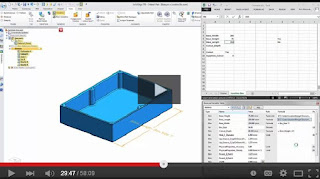
Edge, KSEC is now able to show large 3D assembly models rather than 2D paper drawings. "A 3D model communicates a complex assembly far more effectively than drawings. Teams can now quickly visualize design intent, which lets them more effectively evaluate new products at design reviews," said Fu Ya Li, director of the KSEC information center. http://ow.ly/MiRJw


Try Solid Edge for free

Learn how Solid Edge can save you time on design and development at http://allyplm.com/solidedge/ or sign up for an informative webinar at http://allyplm.com/futureofcad/

Wednesday, December 9, 2015

Anglo Platinum designs better with Solid Edge

The mining machinery maker moved from 2D to 3D CAD and, with Solid Edge (Siemens PLM Software), reducing mine design time up to 12 months. Drawing/design man hours are saved by using 3D designs and automating the generation of 2D drawings. Anglo Platinum recorded significant savings in engineering, construction and interest costs. "Switching to 3D CAD has helped us reduce the time required to design, fabricate and construct a 200,000-ton-per-month mine complex significantly," said Len Pretorius, general manager for project services at Anglo Platinum.


Try Solid Edge for free

Learn how Solid Edge can save you time on design and development at http://allyplm.com/solidedge/ or sign up for an informative webinar at http://allyplm.com/futureofcad/

Friday, December 4, 2015

NX Tip of the Week December 4


NX Tip of the Week
December 4, 2015

NX - Exporting to a Spreadsheet from Navigator 

Hello everyone,

In this week's Ally PLM Tip of the Week, we will take a look at a how to export content from the Assembly Navigator.  In any navigator window, we can configure the content that shows up in the columns.  Once these columns are configured, we can easily export this information to a spreadsheet for capture.

Here is a short video that demonstrates this tip:


Thank you,
Brandon Carter
Senior Application Engineer
Ally PLM Solutions, Inc.


Want more tips? Sign up HERE to receive our Tip of the Week. 
Register for upcoming free NX webinars or learn more about Ally PLM Solutions.

Wednesday, December 2, 2015

Diamond Systems designs better with Solid Edge

Food processing machinery maker upgrades from 2D to 3D design and cuts change orders by 40 percent with Solid Edge (Siemens PLM Software). The move to 3D also results in first prototypes being ready for field testing and that other preliminary prototypes are no longer needed. With the competition still presenting 2D drawings to customers, Diamond Systems' industry-leading reputation has been ensured.


Try Solid Edge for free

Learn how Solid Edge can save you time on design and development at http://allyplm.com/solidedge/ or sign up for an informative webinar at http://allyplm.com/futureofcad/

Tuesday, November 24, 2015

AMF Canada designs better with Solid Edge

Bakery equipment manufacturer shrinks design time 50 percent and assembly time 20 percent by moving from 2D CAD to 3D Solid Edge (Siemens PLM Software). Sheet metal rework was almost completely eliminated. Because delivery times were met and less overtime was needed, AMF reported a boost in profits. "We saw going to 3D as a blessing,” said Marc Stringer, CAD coordinator at AMF. “With Solid Edge, we can achieve the same level of quality in less time.”


Learn how

http://www.plm.automation.siemens.com/en_us/about_us/success/case_study.cfm?Component=30590&ComponentTemplate=1481

Try Solid Edge for free

Learn how Solid Edge can save you time on design and development at http://allyplm.com/solidedge/ or sign up for an informative webinar at http://allyplm.com/futureofcad/

Friday, November 20, 2015

NX Tip of the Week November 20


NX Tip of the Week
November 20, 2015

NX - Editing the Post Processor in NX CAM

In NX CAM, you can edit the standard post processor list enabling you to add your own post processors to the list. You can also reorder the list according to the posts you use most frequently. This can be very useful because this keeps you from having to browse to a certain post that wasn't in the list when your software was installed.  

Here is a short video that shows the standard post list, adding a post to the list, deleting posts from the list, and re-ordering the post list:


Thank you,

Chad Varney
Application Engineer
Ally PLM Solutions, Inc


Want more tips? Sign up HERE to receive our Tip of the Week.


Register for upcoming free NX webinars or learn more about Ally PLM Solutions.

Wednesday, November 18, 2015

Toshiba designs better with Solid Edge

This radar and radio systems manufacturer moved from 2D to 3D CAD and cuts design errors 75 percent with Solid Edge (Siemens PLM Software). Fewer design errors translated into saving money (9 million Japanese yen) saved across several projects. Manufacturing time declined 30 percent and overall task time dropped 50 percent across design, manufacturing and validation. “With the implementation of Solid Edge, we began doing all design work in 3D, starting with basic design. One of benefits of this is that it is now easier to communicate design concepts to others in the company,” said Takaya Ogawa, Komukai operations at Toshiba.


Try Solid Edge for free

Learn how Solid Edge can save you time on design and development at http://allyplm.com/solidedge/ or sign up for an informative webinar at http://allyplm.com/futureofcad/

Tuesday, November 17, 2015

Announcing Maintenance Pack 3 for Solid Edge ST8

Download the Solid Edge ST8 Microsoft Installer (MSI) Maintenance Pack 3 now. 

Microsoft Installer (MSI) Maintenance Packs:
Beginning with Solid Edge ST8, Maintenance Packs are delivered as and installed using Microsoft Installer (MSI) technology. Solid Edge MSI based Maintenance Packs are installed and tracked as Product Updates. 
  • MSI Product Updates can be applied on top of the base release and or existing Product Update with a lesser version. 
  • MSI Product Updates are all inclusive with fixes delivered in MP3 include all fixes delivered in MP1 and MP2. 
  • MSI Product Updates calculate free disk space before installing. Be paitient - note that there have been cases where the Disk Space Computation can take several minutes to complete. 
  • MSI Product Updates can be uninstalled without having to remove the base Solid Edge product. 
  • Uninstalling a MSI Product Update will restore the installation to the state before the Product Update was applied.
  • PLEASE NOTE: When uninstalling a MSI Product Update, the original source media and the previous Product Update package, if any, must be available to allow the recovery of previous file versions.
  • The current MSI Product Update will be the only Update listed and available for uninstallation. After the current Update is uninstalled, the previous Update will become the current Update, if there were multiple Updates installed.
  • MSI Product Updates are uninstalled via the Control Panel (Uninstall a program –> View installed updates -> Uninstall). 
Solid Edge Maintenance Packs are released for CRITICAL items only. Maintenance Packs are available up to 15 months following the release date of the English version. The release date for Solid Edge ST8 English was 06/05/15, making the Maintenance Pack cutoff date 09/05/16.

Solid Edge - Solid Edge ST8 MP3 or later supports Windows 10 if the Windows 10 “November Refresh” version 1511 (OS Build 10586.0) or later is installed.  Solid Edge does not support the new Windows 10 browser, Microsoft Edge.

Solid Edge Integration to Teamcenter - The Solid Edge integration to Teamcenter 10.1.5 and later have been tested on Windows 10 connected to Teamcenter 10.1 and 11.2 servers and there are no known issues.  Teamcenter plans to announce support of Windows 10 with Teamcenter 10.1.6 and 11.2.2.

Solid Edge SP - ST8 Solid Edge SP cannot support Windows 10 due to the following unresolved PR assigned to Microsoft: PR 7410688 - Win 10 does not show the SESP Preview/Properties Card or Edit Properties. 

ST8 Maintenance Packs can be downloaded from:

The Ally PLM Technical Support Team is available to answer any questions and provide support for all of your needs including Maintenance packs. You can contact the Ally PLM Technical Support Team via email at technical.support@allyplm.com or via phone at (513) 984-0480 Option: 4.

Friday, November 13, 2015

Solid Edge Tip of the Week November 13


Solid Edge Tip of the Week
November 13, 2015

Solid Edge - Document Name Enhancements
A lot of times, the information provided to you in the pathfinder can be lacking:


This can be improved with the document name formula in the Solid Edge options:


Clicking Change brings up the Document Name Formula pop-up:


Here you can add text before or after the [Filename] including other properties of that part file:


You can add properties like the material, project name, author and many other properties making a glance at the pathfinder much more informative:


I hope you found this information useful!

Thanks,
Navjot Gill
Application Engineer
Ally PLM Solutions, Inc.

Want more tips? Sign up HERE to receive our Tip of the Week. 


Register for upcoming free Solid Edge webinars or learn more about Ally PLM Solutions.


Wednesday, November 11, 2015

Ricoh designs better with Solid Edge

Office imaging equipment maker effectively and rapidly moves from 2D to 3D product design with Solid Edge (Siemens PLM Software). The move resulted in greater collaboration with manufacturing and service divisions as well as improved refinement of prototypes. “The biggest reason for selecting Solid Edge was that it was user friendly. It has greatly accelerated the shift to 3D design and reduced product development time and costs," said Etsuro Kuretani, R&D engineer, Ricoh Company Ltd.

Learn how
Try Solid Edge for free

Learn how Solid Edge can save you time on design and development at http://allyplm.com/solidedge/ or sign up for an informative webinar at http://allyplm.com/futureofcad/

Friday, November 6, 2015

Solid Edge Tip of the Week November 6

Solid Edge Tip of the Week
November 6, 2015

Solid Edge - Turning on the List of Blocks in Solid Edge Draft

In this Ally PLM Tip of the Week, we are going to look at the option to display existing blocks on a Solid Edge drawing. If you are not familiar with blocks, they are groups of 2D geometry. Native 2D geometry can be blocked within Solid Edge draft or blocks from .dwg can be read into Solid Edge. 

1) Open a drawing that has blocks. This may be a native Solid Edge file or something opened from AutoCAD:

Blocks:

2) Over in the Library tab, toggle on the "Show Blocks" command:  

3) Notice the Block names will be listed under Active Document:

4) We can also select blocks from other drawings and use them in our active document. Select a dft/dwg from the folder above. Notice the preview of the block in the lower window.  CB Network protect is a block on the Circuit Protectors.dft file:

5) Drag and drop the block into the active drawing: 

6) We can create our own blocks using the block command. To find out more information on the Block command, search the Help or click F1 on the keyboard once in the Block command: 


7) There are sample blocks/block libraries delivered in the installation directory of Solid Edge here:  C:\Program Files\Solid Edge ST?\Sample Blocks:

In this week's Tip of the Week, we looked at how to display blocks in active and selected documents. For more information, check out our Ally PLM Lunch Bytes session on 2D Diagramming and Schematics: http://solidedgevideos.blogspot.com/2012/09/solid-edge-diagrams-and-schematics.html

Brandon Carter
Senior Application Engineer
Ally PLM Solutions, Inc.

Want more tips? Sign up HERE to receive our Tip of the Week.

Register for upcoming free Solid Edge webinars or learn more about Ally PLM Solutions.

Wednesday, November 4, 2015

Victor Taichung Machinery designs better with Solid Edge


Machine tool manufacturer moves from 2D to 3D CAD, reducing design to manufacturing time with Solid Edge (Siemens PLM Software). The move resulted in higher engineering productivity and customer satisfaction. "Using Solid Edge to integrate the design process for our machines has significantly improved our productivity," said Stanly Tsai, project engineer at Victor Taichung.


Learn how

Try Solid Edge for free

Learn how Solid Edge can save you time on design and development at http://allyplm.com/solidedge/ or sign up for an informative webinar at http://allyplm.com/futureofcad/

Thursday, October 29, 2015

Ally PLM's presentation of Design Configuration using Excel and the Variable Table at SEU 2015

Ben Weisenberger gave an outstanding standing-room only presentation, Design Configuration using Excel and the Variable Table, at this year's Solid Edge University 2015 in Cincinnati, Ohio. Ben's presentation shows how the variable table and Excel can help make consistent changes among the different parameters.

Watch it now:

Ben Weisenberger is an Application Engineer at Ally PLM Solutions with more than 5 years of Solid Edge experience.

Tracy Tijan
Marketing Director
Ally PLM Solutions

Elephant designs better with Solid Edge

Innovation consultant attains faster, more accurate designs with Solid Edge (Siemens PLM Software). Other results included better decision making at the design stage, problems detected and corrected early, saving development time and an increase in business opportunities. “We are able to get more customers with these visualization tools as we can showcase more options,” said Designer Anand Palsodkar.


Try Solid Edge for free

Learn how Solid Edge can save you time on design and development at http://allyplm.com/solidedge/ or sign up for an informative webinar at http://allyplm.com/futureofcad/


Thursday, October 22, 2015

Hyundai Motor Co. designs better with Solid Edge


The automotive OEM jig and fixture department easily handles large assembly design with Solid Edge (Siemens PLM Software). Hyundai developed libraries and an automation program to enhance the productivity of jig design. The company also can share design libraries with other automotive component suppliers.


Try Solid Edge for free

Learn how Solid Edge can save you time on design and development at http://allyplm.com/solidedge/ or sign up for an informative webinar at http://allyplm.com/futureofcad/

Friday, October 16, 2015

NX Tip of the Week October 16

NX Tip of the Week
October 16, 2015

NX - Using the In Process Workpiece for
Multiple Setups in NX CAM

You can use the In Process Workpiece (IPW) for multiple setups in NX CAM making programming easier and more efficient.  Using the IPW as Blank Geometry can help you visualize the material that has already been cut and also allow NX to create very efficient operations without excessive tool path motion.  The steps below will show the process for using the IPW in a part that requires multiple setups.

1)  The part starts out with the blank defined using a bounding block:

2)  After the operations on the first setup have completed the IPW looks like this:

3)  Now I will use the IPW option to define the blank for the second setup:

4)  Select Source for IPW:

5)  Use the WORKPIECE from the first setup:

6)  Use the Update button to load the IPW from the first setup:

7)  Notice the IPW displays with the operations from the first setup complete:

8)  This shows the second setup operations have been completed and now the IPW is ready for the third setup:


Thank you,
Chad Varney
Application Engineer
Ally PLM Solutions, Inc.

Want more tips? Sign up HERE to receive our Tip of the Week.

Register for upcoming free NX webinars or learn more about Ally PLM Solutions.

Wednesday, October 14, 2015

Space Dynamics Laboratory designs better with Solid Edge

Space-borne instruments research and development company dramatically improved project turnaround with Solid Edge (Siemens PLM Software). Using synchronous technology in Solid Edge, the company gained a 30-fold improvement in fixing open surfaces from vendor files, with gaps now resolved in minutes versus hours. Other results included faster responses to project requests and greater customer satisfaction.


Try Solid Edge for free

Learn how Solid Edge can save you time on design and development at http://allyplm.com/solidedge/ or sign up for an informative webinar at http://allyplm.com/futureofcad/

Friday, October 9, 2015

NX Tip of the Week October 9


NX Tip of the Week
October 9, 2015

NX - Surfacing Tools

Hello everyone - In this week's Ally PLM Tip of the Week, we will take a look at a few different surfacing tools within NX.  I'm defining surfacing tools as any tool required to get more than just a simple shape; more than just extrude or revolve.  The underlying curves are what give the surface definition.  The surface is only as good as the underlying curves.  You may have asked yourself, which surfacing command should I use to create my desired shape?  For example, if we are trying to loft a shape from section to section, you may be trying to determine the difference between Through Curves and Through Curves Mesh.  We will look at the requirements for some of these commands as well as some of the options.  All of these commands have the option to create a solid or sheet (surface) in the settings. 

When defining a surface we look at something called U and V lines.  U and V lines are the definitions for a surface.  Imagine you take a surface and mesh it.  The lines in one direction will be U direction and the lines perpendicular to the U lines will be V lines.

Typically, when we are defining the curves to create our surface, sections will be in one direction (U direction) and the cross curves will be in the other direction (V direction), for example.

Let's take a look at some of these commands:
1) Ruled Surface
Ruled surface requires two sections and only two sections.  The result uses a lofting technique from one section to the other.

2) Through Curves 

Through Curves requires a minimum of two sections, but can have more than two.  This is a lofting technique that can do more than two sections.

3) Through Curves Mesh 

Through Curves Mesh requires a minimum of two sections, but can have more than two.  It also requires a minimum of two cross curves, but can have more than two.  Cross curves are typically defined in the perpendicular direction to the section inputs.  This technique lofts from section to section and applies the cross curve definitions in the other direction.  The cross curves must be connected to the sections.

4) Studio Surface 

Studio Surface is similar to Through Curves Mesh as far as definition.  It produces swept for lofted features from a network of section strings, or a network of section strings and up to three guide strings.  It requires at least two inputs.  It can be two sections or one section and one guide/cross curve at minimum.  Studio Surface also has some other options for flexibility within the feature.  Studio Surface can create lofted shapes or swept shapes within the same command. Studio Surface also previews as soon at two inputs are defined.  The cross curves do not have to be connected to the cross sections to get a result.  

Studio Surface has an option called "Switch Strings" which can toggle your U and V line definition curves: 

5) Sweep Along Guide 

Sweep Along Guide requires one section and one guide curve.  It takes the section and sweeps it down the guide definition.

6) Tube 

Tube just needs a path definition.  The cross section is determined to be circular with tube parameters included.

7) Swept

Swept takes a cross section definition and sweeps it along a path.  It can have multiple sections but only up to three guide strings.  In the screen shot below, the section and guide curve is not connected.  They do not need to be connected for the swept algorithm.

8) Variational Sweep 

Variational Sweep takes a profile and sweeps it between two curves or surface edges.  Because it is a sweep, the sketch section is created with the on path option.  How the sketch is connected to the surface edges/curves determines its sweep path.  It varies as it transitions between the input curves.  You can sweep faces that are coincident, tangent, or normal to other curves and faces, add secondary sections to vary dimensions at specific locations, or extend the body beyond the length of the path or limit it.

In this Ally PLM Tip of the Week, we took a look at some of the requirements for the different surfacing tools.  This information can help you pick the proper feature for your desired surface requirement.

Brandon Carter
Senior Application Engineer
Ally PLM Solutions, Inc.

Want more tips? Sign up HERE to receive our Tip of the Week. 

Register for upcoming free NX webinars or learn more about Ally PLM Solutions.