This Blog has Moved

This blog has moved to www.allyplm.com/blog

To stay up-to-date with the latest news, tips and tricks, product enhancements and maintenance packs for Siemens PLM Software solutions, visit our new site!

For resources for specific products, you can navigate directly to the product resource page:
... and more!
Showing posts with label NX. Show all posts

Thursday, February 18, 2016

How to Convert Part Units in NX


The example below shows how to convert a Metric part file to Inches.  The process to convert an Inch file to Metric is the same, with one exception noted in step 3.
1. Close the part you want to convert:
2. Go to Start>All Programs>Siemens NX?? Folder>NX Tools and select the “Command Prompt”:
3. In the command prompt type: ug_convert_part-in and then drag the part into the Command Prompt window and press enter:(note: replace -in with -mm to convert to metric)
4. You will see the report in the Command Prompt window:
5. Open the part and verify that the Units have changed:

Friday, December 4, 2015

NX Tip of the Week December 4


NX Tip of the Week
December 4, 2015

NX - Exporting to a Spreadsheet from Navigator 

Hello everyone,

In this week's Ally PLM Tip of the Week, we will take a look at a how to export content from the Assembly Navigator.  In any navigator window, we can configure the content that shows up in the columns.  Once these columns are configured, we can easily export this information to a spreadsheet for capture.

Here is a short video that demonstrates this tip:


Thank you,
Brandon Carter
Senior Application Engineer
Ally PLM Solutions, Inc.


Want more tips? Sign up HERE to receive our Tip of the Week. 
Register for upcoming free NX webinars or learn more about Ally PLM Solutions.

Wednesday, December 2, 2015

NX Licensing Issue regarding Include Statement

I thought I would share this NX Licensing issue as it was a tough one:

1.       I asked for a new NX license file to install NX on my machine that has the TC Server working on the VM.  I received a license file, but could not get it to work.  I kept getting this (I removed the ip address and servername for privacy…
Flexible License Manager status on Wed 12/2/2015 10:28
[Detecting lmgrd processes...]
Error getting status: License server machine is down or not responding.
See the system administrator about starting the license server system, or
make sure you're referring to the right host (see LM_LICENSE_FILE).
Hostname:      XXX.XXX.XXX.XXX
License path:  28000@servername;
FLEXnet Licensing error:-96,491
For further information, refer to the FLEXnet Licensing documentation,
available at "www.flexerasoftware.com".
____________________________________________________________________________
2.       Looking at the log file I saw this.  With about 30 of the INCLUDE missing things listed. 

10:53:00 (ugslmd) USER_BASED license error for prd_ps_teamcenter_access (INCLUDE missing)
10:53:00 (ugslmd) USER_BASED license error for prd_vkrc1_ps_controller (INCLUDE missing)
10:53:00 (lmgrd) ugslmd using TCP-port 53740
11:04:23 (lmgrd) ugslmd exited with status 58 ()
11:04:23 (lmgrd) Since this is an unknown status, license server
11:04:23 (lmgrd) manager (lmgrd) will attempt to re-start the vendor daemon.
11:04:23 (lmgrd) EXITING DUE TO SIGNAL 1

3.       So I knew that it was reading the license file and the CID had to be right or it would error on that.  I had never seen this before.  I knew this had to do with the Flex options file as INCLUDE is a statement in the options file.  I did some googling and found that this was looking for the options file to have a list of users for these features.   What I did not know was why as this was not the way it was before – GTAC did not know why either.  So, I called the guy I know at Siemens that is the most knowledgeable person on licensing.  He had not seen it either so he talked to the developers.  Here is his response to me.

So what we have found out is that the TCDIST is a user based license and it actually requires an options file.  All of the following lines are because of the missing options file that would have the INCLUDE line in it:

(ugslmd) USER_BASED license error for planner export (INCLUDE missing)

The options file is just a text file and has to be named ugslmd.opt  I have attached the one that I used.  There is one thing that I did find with this is that the file is case sensitive.
You should be able to put this file in your directory and restart the flexlm service and it should start with no errors. You can change the user names to fit your environment and users.

4.       So now I created an Options file and tried to get it to work (see my blog post on Flex options files at http://allyplm.com/knowledgebase/2014/9/26/reserving-a-license-for-an-individual-or-group?rq=options%20flex).  However, NX requires you to use the name ugslmd.opt and you do not need to add it to the license file.  It must be located in the same directory as the license file and they both must be in the Siemens…PLMLicenseSever directory of the license server install.  Here is what is in my options file contained (just a notepad file renamed ugslmd.opt).  You have to have the same amount of Includes as licenses available.  Since, I have 4, I have to have four usernames (replace WindowsUserName with your NX users Windows User Login Name).  When I put in 5, it gave an error saying I had 5 in the log file and the max was 4.

INCLUDE TCDIST USER WindowsUserName1
INCLUDE TCDIST USER WindowsUserName2
INCLUDE TCDIST USER WindowsUserName3
INCLUDE TCDIST USER WindowsUserName4

5.       So, I did a stop, start, reread as I usually do.  I got a license reread failed at the bottom of LMTools.exe.  Talking again with my license guru revealed that in the middle of the log file, you see the following:

11:59:30 (ugslmd) NOTE: Some features are USER_BASED or HOST_BASED
11:59:30 (ugslmd)   If a reread is done, and the INCLUDE list changes for these
11:59:30 (ugslmd)   there is a delay of 12 hours for this to take effect.
11:59:30 (ugslmd)
11:59:30 (ugslmd) Licenses are case sensitive for ugslmd

6.       So, even though it said failed, it was ok.  I loaded NX and was able to open it fine.  It was just that I had to have an options file for the include statements. 


Madison Rye
Application Engineering Manager
Ally PLM Solutions, Inc.

Monday, November 23, 2015

Maintenance Release 3 for NX 10.0.3 is now available

Maintenance Release NX 10.0.3 is now available for download from the Siemens PLM download server. NX 10.0.3 is an accumulation of fixes built for installation on top of Windows 64-Bit, Linux 64-Bit and Mac OS images of NX 10.0.0.

To download this Maintenance Release, Maintenance Release Documentation, or to review the README files, select the following link or enter the URL in your browser address window:
https://download.industrysoftware.automation.siemens.com/download.php

From the Product Download page, enter “10.0.3” (including the quotes) in the Search box to see a list of links to the release letter and available release packages.

Alternatively, the release packages can be found using the file navigator by selecting ‘NX’ from the list of products and then navigating through the directory structure by selecting:
Product updates --> Maintenance-release --> NX10 --> [platform].

If you encounter any problems installing this maintenance pack, please contact Ally PLM Solutions www.allyplm.com 513.984.0480.

Tracy Tijan
Marketing Director
Ally PLM Solutions

Friday, November 20, 2015

NX Tip of the Week November 20


NX Tip of the Week
November 20, 2015

NX - Editing the Post Processor in NX CAM

In NX CAM, you can edit the standard post processor list enabling you to add your own post processors to the list. You can also reorder the list according to the posts you use most frequently. This can be very useful because this keeps you from having to browse to a certain post that wasn't in the list when your software was installed.  

Here is a short video that shows the standard post list, adding a post to the list, deleting posts from the list, and re-ordering the post list:


Thank you,

Chad Varney
Application Engineer
Ally PLM Solutions, Inc


Want more tips? Sign up HERE to receive our Tip of the Week.


Register for upcoming free NX webinars or learn more about Ally PLM Solutions.

Monday, November 16, 2015

Just Released - Maintenance Pack 04 for NX 10.0.2

Maintenance Pack 4 (MP04) for NX 10.0.2 is now available and you can download it from the Siemens PLM download server.
 
To find the release package(s) for your platform(s) click on the following link or enter the URL in your browser address window. A valid WebKey account is required.:

https://download.industrysoftware.automation.siemens.com/download.php

From the intial page, enter "10.0.2.mp4" (including the quotes) in the Search box to see a list of links to the release letter and available release packages.

Alternatively, the release packages can be found by selecting the 'NX/Unigraphics NX' tab and then navigating through the directory structure by selecting > Product updates > Maintenance-packs > NX10 > [platform].
   
If you encounter any problems installing this maintenance pack, please contact Ally PLM Solutions www.allyplm.com 513.984.0480.

Tracy Tijan
Marketing Director
Ally PLM Solutions

Friday, October 16, 2015

NX Tip of the Week October 16

NX Tip of the Week
October 16, 2015

NX - Using the In Process Workpiece for
Multiple Setups in NX CAM

You can use the In Process Workpiece (IPW) for multiple setups in NX CAM making programming easier and more efficient.  Using the IPW as Blank Geometry can help you visualize the material that has already been cut and also allow NX to create very efficient operations without excessive tool path motion.  The steps below will show the process for using the IPW in a part that requires multiple setups.

1)  The part starts out with the blank defined using a bounding block:

2)  After the operations on the first setup have completed the IPW looks like this:

3)  Now I will use the IPW option to define the blank for the second setup:

4)  Select Source for IPW:

5)  Use the WORKPIECE from the first setup:

6)  Use the Update button to load the IPW from the first setup:

7)  Notice the IPW displays with the operations from the first setup complete:

8)  This shows the second setup operations have been completed and now the IPW is ready for the third setup:


Thank you,
Chad Varney
Application Engineer
Ally PLM Solutions, Inc.

Want more tips? Sign up HERE to receive our Tip of the Week.

Register for upcoming free NX webinars or learn more about Ally PLM Solutions.

Friday, October 9, 2015

NX Tip of the Week October 9


NX Tip of the Week
October 9, 2015

NX - Surfacing Tools

Hello everyone - In this week's Ally PLM Tip of the Week, we will take a look at a few different surfacing tools within NX.  I'm defining surfacing tools as any tool required to get more than just a simple shape; more than just extrude or revolve.  The underlying curves are what give the surface definition.  The surface is only as good as the underlying curves.  You may have asked yourself, which surfacing command should I use to create my desired shape?  For example, if we are trying to loft a shape from section to section, you may be trying to determine the difference between Through Curves and Through Curves Mesh.  We will look at the requirements for some of these commands as well as some of the options.  All of these commands have the option to create a solid or sheet (surface) in the settings. 

When defining a surface we look at something called U and V lines.  U and V lines are the definitions for a surface.  Imagine you take a surface and mesh it.  The lines in one direction will be U direction and the lines perpendicular to the U lines will be V lines.

Typically, when we are defining the curves to create our surface, sections will be in one direction (U direction) and the cross curves will be in the other direction (V direction), for example.

Let's take a look at some of these commands:
1) Ruled Surface
Ruled surface requires two sections and only two sections.  The result uses a lofting technique from one section to the other.

2) Through Curves 

Through Curves requires a minimum of two sections, but can have more than two.  This is a lofting technique that can do more than two sections.

3) Through Curves Mesh 

Through Curves Mesh requires a minimum of two sections, but can have more than two.  It also requires a minimum of two cross curves, but can have more than two.  Cross curves are typically defined in the perpendicular direction to the section inputs.  This technique lofts from section to section and applies the cross curve definitions in the other direction.  The cross curves must be connected to the sections.

4) Studio Surface 

Studio Surface is similar to Through Curves Mesh as far as definition.  It produces swept for lofted features from a network of section strings, or a network of section strings and up to three guide strings.  It requires at least two inputs.  It can be two sections or one section and one guide/cross curve at minimum.  Studio Surface also has some other options for flexibility within the feature.  Studio Surface can create lofted shapes or swept shapes within the same command. Studio Surface also previews as soon at two inputs are defined.  The cross curves do not have to be connected to the cross sections to get a result.  

Studio Surface has an option called "Switch Strings" which can toggle your U and V line definition curves: 

5) Sweep Along Guide 

Sweep Along Guide requires one section and one guide curve.  It takes the section and sweeps it down the guide definition.

6) Tube 

Tube just needs a path definition.  The cross section is determined to be circular with tube parameters included.

7) Swept

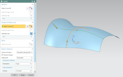
Swept takes a cross section definition and sweeps it along a path.  It can have multiple sections but only up to three guide strings.  In the screen shot below, the section and guide curve is not connected.  They do not need to be connected for the swept algorithm.

8) Variational Sweep 

Variational Sweep takes a profile and sweeps it between two curves or surface edges.  Because it is a sweep, the sketch section is created with the on path option.  How the sketch is connected to the surface edges/curves determines its sweep path.  It varies as it transitions between the input curves.  You can sweep faces that are coincident, tangent, or normal to other curves and faces, add secondary sections to vary dimensions at specific locations, or extend the body beyond the length of the path or limit it.

In this Ally PLM Tip of the Week, we took a look at some of the requirements for the different surfacing tools.  This information can help you pick the proper feature for your desired surface requirement.

Brandon Carter
Senior Application Engineer
Ally PLM Solutions, Inc.

Want more tips? Sign up HERE to receive our Tip of the Week. 

Register for upcoming free NX webinars or learn more about Ally PLM Solutions.


Wednesday, September 23, 2015

FREE Apple Watch when you sign up for Ally PLM Solutions training classes!

Apple Watch is a whole new experience with amazing technologies.
Convenience and customization meeting your own personal needs!


Now you can have your own Apple Watch by signing up for select Ally PLM training classes*. Training classes can be taken at Ally's Corporate Office, online or onsite at your facility.
Click HERE to view course descriptions and register. 


*Qualified classes include Solid Edge Fundamentals, Synchronous Technology for the Ordered User, Solid Edge Advanced Techniques, Essentials for NX Designers, Advanced Techniques for NX Designers, NX CAM Fundamentals, NX CAM Advanced Techniques and CAMWorks Fundamentals

**You may choose the Apple Watch promotion or BOGO - buy one, get one half off qualified training classes  

Friday, August 28, 2015

NX Tip of the Week August 28


NX Tip of the Week
August 28, 2015

NX - Snap to Object
When modeling in NX there are many times where we want to extend a shape to another shape.  For example when using "Pull Face" in Synchronous Modeling, we want to pull a face to be parallel with another existing face on the model.  Of course, we can measure the distance between the 2 faces and input that value into the dialog.  However, there is a shortcut that can save you time and avoid the possibility of accidentally inputting an incorrect value.  The steps below will show how to use "Snap to Object" in the Extrude command when creating blank stock to be used in NX CAM.  Keep in mind that "Snap to Object" is available in multiple commands in NX.
1)  This is the part that I will be programming using NX CAM. In modeling, I will create a blank shape representing the raw material:
2)  Within the Extrude command, I have started the extrude 1.5" from the back of the part:


3)  Since I want the extrude to extend to the front face of the part I will use "Snap to Object" by right clicking on the blue arrow:


4)  Then I will simply pick the face I want to extend to:


5)  As you can see, the extrude is now extended to 5.6" which is parallel to the face of the part:

Thank you,
Chad Varney
Applications Engineer
Ally PLM Solutions, Inc.

Want more tips? Sign up HERE to receive our Tip of the Week. 


Register for upcoming free NX webinars or learn more about Ally PLM Solutions.