This Blog has Moved

This blog has moved to www.allyplm.com/blog

To stay up-to-date with the latest news, tips and tricks, product enhancements and maintenance packs for Siemens PLM Software solutions, visit our new site!

For resources for specific products, you can navigate directly to the product resource page:
... and more!
Showing posts with label NX CAM. Show all posts

Friday, June 19, 2015

Tip of the Week June 19

 NX Tip of the Week
June 19, 2015

NX - Customize Columns and Export Information from NX
to an Excel Spreadsheet
There is a very useful option in NX that allows the user to export information from NX into an Excel spreadsheet. This can be used in NX CAM to export a list of tools, operations, and other information. This could be used in NX CAD to export a list of components in an assembly, model history, etc. The steps below will illustrate how to export machining information and also how to modify columns in the Operation Navigator in NX CAM. Customizing columns will allow you to export only the information needed for the spreadsheet.

1)  In the Manufacturing Environment, I am in the Program Order View. Notice the list of operations and the information listed in each column: 

2)  Right click below the operations in the Operation Navigator and then select "Export to Spreadsheet":

3)  Notice all of the information from the Operation Navigator is now listed in an Excel spreadsheet:

4)  Customize the columns by right clicking below the operations in the Operation Navigator and select "Columns" and check and uncheck the columns you want to display:

5)  Notice I have turned on the "Time" column and now the time of each operation is shown in the spreadsheet:

Chad Varney
Application Engineer
Ally PLM Solutions, Inc.

Want more tips? Sign up HERE to receive our Tip of the Week.
Register for upcoming free NX webinars or learn more about Ally PLM Solutions.

Friday, May 15, 2015

Tip of the Week May 15


NX Tip of the Week
May 15, 2015

NX - Using Patch Openings in NX CAM

When trying to machine contoured surfaces with contour milling operations in NX CAM you may have issues with holes or gaps interfering with your tool path.  An example may be a mold or die insert that bolts into a pocket.  The part may have counter bored holes that break through the contoured shape you need to machine.  These holes can be easily covered using "Patch Opening" allowing the toolpath to travel smoothly across the part without trying to cut inside the hole.  An example (shown below) illustrates how to use "Patch Openings" to optimize a Z level operation. 

1)  Notice the tool path tries to cut inside the holes causing unwanted machining time: 

2)  Selecting only the faces that need to be cut causes excessive engage and retract moves:
3)  Use "Patch Openings" to cover the hole shapes:


4)  I have selected the contoured faces and the edge of the hole: 

5)  The faces must be added to the WORKPIECE: 


6)  Notice the tool path cuts smoothly across the hole:

Chad Varney 
Application Engineer
Ally PLM Solutions, Inc.

Want more tips? Sign up HERE to receive our Tip of the Week.


Register for upcoming free NX webinars or learn more about Ally PLM Solutions.

Friday, April 10, 2015

Tip of the Week April 10


NX Tip of the Week
April 10, 2015

NX - Avoiding Collisions in Drilling Operations in NX CAM

When using the Drilling operation in NX CAM sometimes you may have issues with the tool colliding with the workpiece when the tool traverses from one hole to another if there is a feature between the two holes. If the feature isn't especially tall you can simply adjust the "Minimum Clearance" distance to a higher value. However, this adjusts where the tool starts its drilling cycle to a higher value along with the rapid height level causing excessive cycle times. Another way to do this would be to set a value in "Rtrcto" in Cutting Parameters but this could also cause a longer cycle time. A better way to avoid a collision in a Drilling operation is to use "Avoid" when specifying holes. Below are the steps showing an example of avoiding a tall area on a part in a Drilling operation.

1) Notice the path shown collides with the part. Re-specify the holes and select Avoid:

2) Notice in the cue line in the upper left-select a start point. This is the point before you want the higher retract move. Notice the cursor location in the pic:

3) Pick the end point. This is the point where the higher retracts will stop. Notice the cursor location in the pic:

4) Select "Distance" for the retract height:

5) Notice "Rtrcto" in Cutting Parameters is set to None:

6) After regenerating the operation the tool will rapid up to the distance specified between the 2 points you defined:

Chad Varney 
Application Engineer
Ally PLM Solutions, Inc.

Want more tips? Sign up HERE to receive our Tip of the Week.
Register for upcoming free NX webinars or learn more about Ally PLM Solutions.


Friday, March 20, 2015

Tip of the Week March 20


NX Tip of the Week
March 20, 2015


NX - Ordinate Dimensioning in NX Modeling and Reusing it in Drafting

Today I will explain how to create ordinate dimensions within NX Modeling. I will also show how to reuse the dimensions in Drafting.
     
Ordinate Dimensioning in Modeling Application -


Result in Drafting Environment -

  • To get started, make sure the PMI option is turned ON. By default, it is turned OFF


  • Set the Model View to Work:    


  • Under the PMI Ordinate Dimension command, pick Single or Multiple Dimension.

  • With Single Dimension, use Select Origin where you pick any point. This is going to be the origin of the ordinate dimension.

  • I have selected the single dimension option to help pick one hole at a time:


  •  Start by picking the center of the holes and place them one at a time:


  • Now let's look at the Multiple Selection option. With Multiple Dimension, I can pick all the holes at once.

  • Change the option to Multiple Dimension and pick the origin:


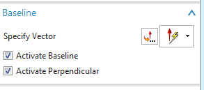
  •  Set the Baseline option:


  •  Before I start selecting the holes, the margins need to be defined. Click on the Define Margins command:


  •   


  •  Here are the options I selected for this example:


  •    


  •  Select the bottom left corner point as the origin:


  •    


  •  Follow the same procedure to get a horizontal margin:


  •  Baseline option step:


  •  Select all the holes by clicking on the center point of the circular edge.

  • Result:


  • Save the Model file.


  • Switch to the Drafting application and place the top model view on the sheet:


  • After placing the view, go to View Settings:


  • Make sure to change the settings to From Model View, click Apply:


  • Final Result:


    Navjot Gill 
    Application Engineer
    Ally PLM Solutions, Inc.

    Want more tips? Sign up HERE to receive our Tip of the Week.


    Sunday, January 18, 2015

    Tip of the Week January 16


    NX Tip of the Week
    January 16, 2015

    NX - Using Custom Boundaries in NX CAM

    In machining, there are often situations where you need to add or remove extra material in a specific area of your part but not the entire part.  In NX CAM, you can apply custom parameters to individual boundary members allowing you to add or remove extra material to a certain area of the part.  A good example of this is when using Planar Mill and editing the Part Boundary to add or remove extra material.  Below are the steps to add extra material to two specific areas of a part.
         
    1)  In the part shown below, a Planar Mill operation cuts a portion of the part detail to finish size:


    2)  For this demonstration we want to add .030" to the faces highlighted below:


    3)  Edit the Part Boundaries:


    4)  Select Edit to be able to edit members individually:


    5)  Use the "Next" arrow to toggle through each individual boundary member.  The active boundary member is shown in orange:


    6)  Once the boundary member is highlighted in orange, select Custom Member Data:


    7)  Apply 0.030" stock to the boundary member:


    8)  Repeat steps 4, 5, 6 & 7 for the second face to which you want to add stock.

    9)  Generate the operation and see that the cutter leaves 0.030" extra material on the desired faces and leaves 0.000" on the rest of the faces:


    Chad Varney
    Application Engineer
    Ally PLM Solutions, Inc.

    Want more tips? Sign up HERE to receive our Tip of the Week.


    Register for upcoming free NX webinars or learn more about Ally PLM Solutions.